Westermo MR-2x0 User Manual
Page 17
17
6622-2221 • 29000447
If the auxilary power connector is being used, the main power connector should
NOT
be used.
Input Signal Information
… Applied input voltage to activate: +4 V to +28 VDC
… Applied input voltage to deactivate: 0 V to +1 VDC
(Negative voltages can be applied to –28 VDC)
… Maximum input current: 3 mA
… Input protection activates at more than ±28 VDC.
External current limiting is needed to protect input voltages above ±28 VDC.
Output Signal Information
… Maximum voltage switched: +28 VDC
… Maximum current switched: +40 mA
… Output leakage current is equivalent to a 10 Kohms resistor to Ground.
… Suggested minimum Relay Coil resistances:
• Supply Voltage 6 VDC, minimum resistance 100 Ohms
• Supply Voltage 12 VDC, minimum resistance 240 Ohms
• Supply Voltage 24 VDC, minimum resistance 480 Ohms
… The output switch is protected against back-EMFs generated at relay turn-off.
… Output protection activates at more than ±28 VDC.
External current limiting is needed to protect input voltages above ±28 VDC.
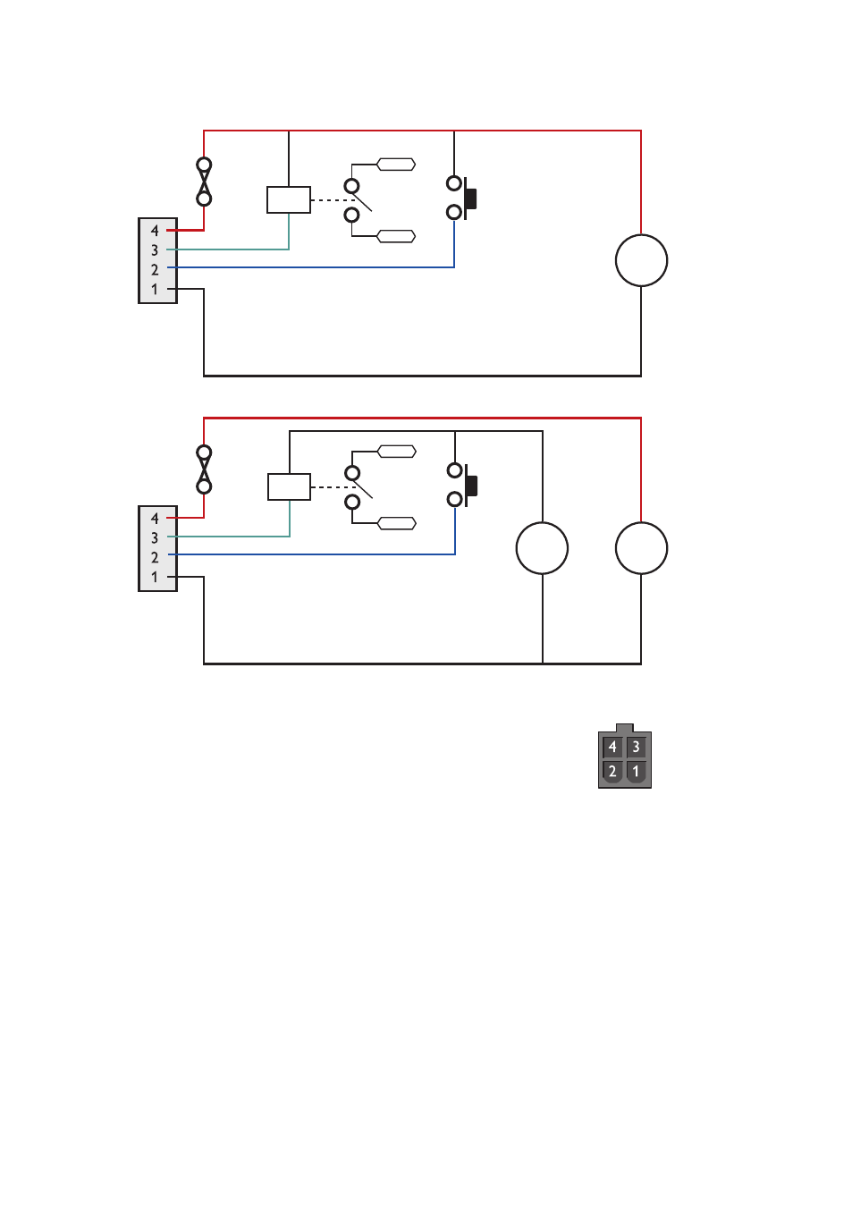
POWER
11 – 28 V
Relay
Switch
INPUT/OUTPUT
INPUT
GND
+
–
POWER
GND
11 – 28 V
+
–
4 – 28 V
+
–
1 Input, 1 Output, Supply Voltages up to 28 VDC
1 Inputs, 1 Output, Supply Voltages up to 58 VDC
Relay
Switch
INPUT/OUTPUT
INPUT
Connector Pin Numbers