Safety control drawing – Westermo RFI-xx User Manual
Page 8
8
6641-22305
M5 threaded hole
for Pe connection
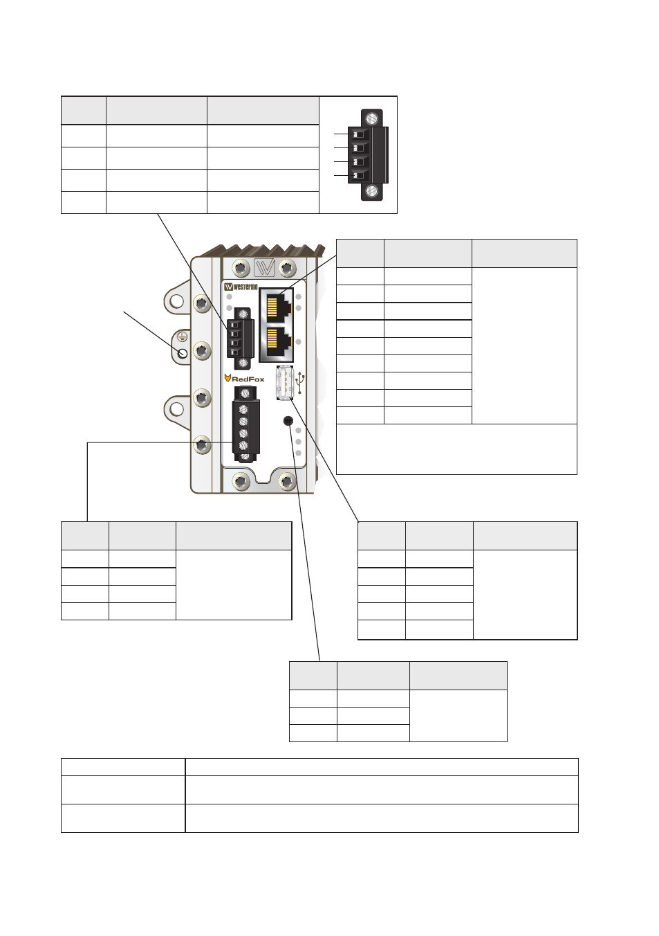
Safety control drawing
Position Direction* /
description
input / Output values
1
2
3
4
1
iO / relay output +
U
in
= 60 VDC max
2
iO / relay output –
i
in
= 80 mA max
3
iO / Digital in +
U
in
= 60 VDC max
4
iO / Digital in –
i
in
= 10 mA max
Position Direction* /
description
Output values
1
Out / VBUs
U
out
= 5 VDC max
i
out
= 500 mA max
2
in/out / D–
3
in/out / D+
4
GND
shield
Pe
Position Direction* /
description
input values
1
in / +DC1
U
in
= (16 – 60) VDC
i
in
= 1.5 A @ 16 VDC
P
in
= 24 W @ 16 VDC
2
in / +DC2
3
in / COM
4
in / COM
Position Direction* /
description
input/output values
1
in/out / GND
U = 3.3 VDC max
i = 24 mA max
2
Out / Tx
3
in / rx
Degree of protection:
iP 40
Ambient temperature:
–40°C to +70°C (–40°F to +158°F). (rFi-10-F4G-T4G and rFi-18-F4G-T4G requires
forced air flow at operating temperatures above 60°C 140°F)
installation spacing:
Minimum 25 mm above/below
Minimum 10 mm left/right
* Direction relative this unit!
FRNT
+DC1
+DC2
COM
COM
ST1
ST2
ON
DC1
DC2
1
2
POWER
CONSOLE
IO
Position Direction* /
description
input/output values
1
in/out / TD+
Per port:
U = ± 1 V (4μV/s)
i = ± 20 mA
Data rate:
10/100 Mbit/s
2
in/out / TD–
3
in/out / rD+
4
Not connected
5
Not connected
6
in/out / rD–
7
Not connected
8
Not connected
shield
Pe
Galvanically isolated via signal transformers and
capacitively isolated to GND/Pe through a 2kV
1000pF capacitor.
see user manual for proven transient protection.