Ethernet 1, Led indicators – Westermo EDW-120 User Manual
Page 25
25
6616-2211
LED
Status
Description
PWR
OFF
No internal power
ON
Internal Power OK
TD
(A and B)
OFF
No serial data transmitted from A and B: RS-232
ON
Serial data transmitted from A and B: RS-232
RD
(A and B)
OFF
No serial data received to A and B: RS-232
ON
Serial data received to A and B: RS-232
LINK
OFF
No Ethernet link.
Cable not connected.
ON
Good Ethernet link.
Flash
Ethernet data is transmitted or received, traffic indication.
STAT
OFF
Normally Off
ON
Telnet session established to Telnet diagnostics service or
Ongoing configuration by Web tool.
RC
OFF
DIP switch settings are valid.
ON
One or more DIP switches are overrid by remote configuration.
SPD
ON
Mbit/s
OFF
Mbit/s
DPX
ON
Full duplex
OFF
Half duplex
Position Direction* Signal name Description/Remark
No.1
In
Transmit +
Transmit data
No.2
In
Transmit –
Transmit data
No.3
Out
Receive + (/–) Receive data, auto-polarity***
No.4
–
-
Terminated
No.5
–
-
Terminated
No.6
Out
Receive – (/+) Receive data, auto-polarity***
No.7
–
–
Terminated
No.8
–
–
Terminated
Shield
–
Shield
HF-connected to COM (via capacitor)
8
7
6
5
4
3
2
1
Ethernet 1
(Auto-Negotiation disabled**)
CAT 5 cable is
recommended.
Unshielded (UTP)
or shielded (STP)
connector might
be used.
*
Direction relative this unit.
**
Disable auto-negotiation also disables auto crossover (auto MDI/MDI-X).
***
Auto-polarity always enabled an only relevant for 10BaseT.
NOTE! Pin number and signal name relations might be changed by auto crossover or
auto polarity.
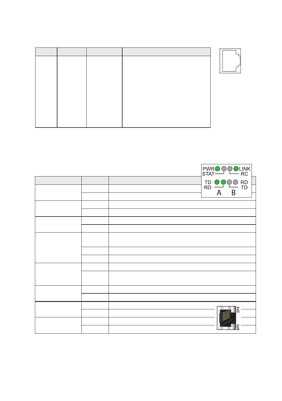
LED Indicators
Power
Transmit data
Receive data
Status
Remotely controlled
Speed Integrated in RJ-45
Green
Duplex Integrated in RJ-45
Yellow