Line arrays – X-Treme Audio MISI User Manual
Page 11
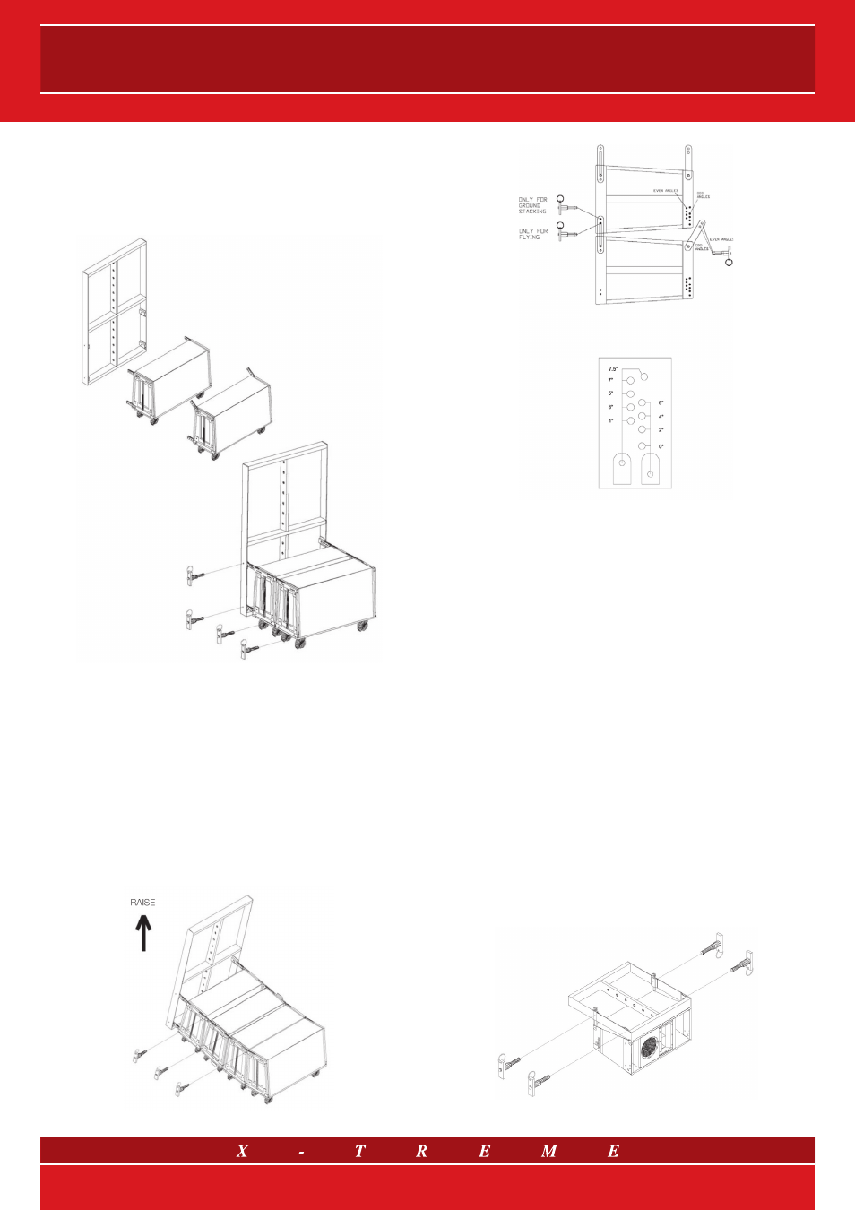
When a certain number of speaker systems are lifted (fig. 14 shows
a line array system configuration in which the first two modules are
made up of flying subwoofers and the others of line ar ray elements
with a standard type of installation), they should be inter-connected
(between them) on the floor, placing them on special wheelboards.
Then follow the procedure shown in the following figure.
fig. 15
Slide the metallic joints of each loudspeaker system in the insert of the
handle of the next system, fixing them with the pins in the final part only,
which corresponds to the front part of the speakers (fig. 15).
In the curved arrays, the vertical dispersion angles must be inversely
proportional to the distance from the listening point. For example,
regarding the farthest positions, the dispersion angle will be small,
and will increase progressively as the listening point gets closer to the
linear array. The coverage angle of the curved array is given by the di-
mension or height of each speaker, the incli nation angle between the
speakers and the number of units to be suspended. The maximum
inclination angle between two Linear Source Array modules is 7.5°.
fig. 16
fig. 17
Depending on the hole in which the (
XT-PIN) pin is inserted in the
upper part of the speaker system, the acoustic speaker systems will
be arranged according to a specific angle. Lifting the structure with
the hung loudspeaker systems and sliding the pins into the upper
groove, on the holes delimiting the selected angles, the operation
can be easily carried out as shown in figure 16.
Once the array lifting has been completed, the STD-LSA, STD-MISI
or STD-MLA bars must be fixed to avoid any rotation.
13.5 MISI™ and MLA: enclosure suspension rigging
The
MISI™ and Mini Line Array systems are equipped with a fly-
ing hardware placed on the front and the rear of the acoustic loud-
speaker system.
Two pull-out metallic bars are fitted on both sides of the loudspeaker
system front (in the lower part). By unhooking and sliding out these
two bars, the acoustic enclosure can be fixed to the lower element
(that is the flying bar if the speaker is the first on the floor or any other
line array module). Safe fixing is ensured by sliding the pins into the
corresponding holes of the lower unit.
On both sides of the rear part of the speaker two hinged joints are
fitted; they are used to determine the angle between two succeed-
ing cabinets. By releasing and rotating them, the joints can be fixed
to the upper element (any speaker or the flying bar as for the module
on top of the array), matching the fixing holes with the required angle
and sliding the pins (XT-PIN), as shown in figure 18.
fig. 18
11/21