User’s manual – X-Treme Audio MISI User Manual
Page 12
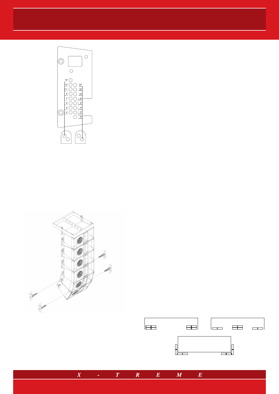
fig. 19
The wheelable metallic joints are equipped with two holes - one
above the other - corresponding to even or odd angles for a secure
fixing, as indicated in figure 19.
Also in this case, the coverage angle of the curved array depends
on the dimensions of each loudspeaker system, the incli nation an-
gle between the speakers and the number of units that must be
suspended. The enclosures will be arranged with a specific angle
(fig. 20) according to the hole in which the pin (XT-PIN) will slide into
on the upper part of the loudspeaker system. The maximum inclina-
tion angle between two subsequent MISI
TM
or MLA modules is 15°.
fig. 20
14. Subwoofers
The subwoofers are used to extend the system frequency response
up to 25-30 Hz and to increase the SPL level at low frequencies
without increasing potential hearing damage to users.
General guidelines for using subwoofers
The number of subwoofers to be used depends on 3 parameters:
1) Number of flying elements
The recommended standard number of subwoofers corresponds to
a
1:1 ratio (1 upper module - 1 subwoofer).
2) Type of programme to be reproduced
The standard subwoofer ratios are recommended for reprodu cing
classical music or for conventions. In these applications subwoof-
ers provide low frequencies extension of the line array modules
and generate contribution of roughly 6 dB in the bands used. In
this case, the resulting audio system will work as a 4-way broad
pass band in tri-amplification mode. In live applications with rock
music reproduction,
1:1.5 ratio (e.g. 2 modules and 3 subwoofers,
4:6, 8:12) or even
1:2 (1 upper module - 2 subwoofers) are recom-
mended for strong reinforcement at low frequencies.
3) Type of location or installation
When the subwoofers are stacked outdoors, the ratios are those
mentioned above. In the case of flying units, a higher number of
subwoofers is required. They are usually installed on the floor,
in a side-by-side configuration, in order to exploit the emphasis
resulting from the floor coupling. When the flying modules and
the subwoofers are physically separated, it is well-known that the
phase alignment is valid in one position only, therefore a suitable
compromise should be reached. When the systems are aligned,
a position that is most representative of the listening area should
be chosen.
It is also well-known that when different subwoofer arrays are placed
on the sides of the stage (left-right),
sums and cancellations will oc-
cur that vary according to the different listening positions.
This phenomenon can be avoided by using the following tech-
niques:
a) using vertical subwoofer arrays placed on the sides of the stage
(e.g.
4-4 left-right configuration). See drw. 21 a);
b) placing n elements on the sides of the stage and 2n elements
in the middle of the stage (e.g.:
left-centre-right 2-4-2 configu-
ration), as shown in drw. 21 b). This ensures better coverage on
the stage axis (where most of the audience is usually found) and
a coherent sound image;
c) physically curving the subwoofer arrays to create an
L-shaped
array rotating around the stage angle, see drw. 21 c). This orientates
the main lobes of the left and right arrays out of the stage axis, thus
reducing the central sum.
It should be stressed that using a central horizontal line array with an
electronic delay limiting its directionality will still generate excessive
sound concentration in the middle of the audience. However, the
advantage of a vertical omnidirectional directivity is achieved, which
makes it a good solution for indoor use.
STAGE
STAGE
STAGE
fig. 21 a)
fig. 21 b)
fig. 21 c)
12/21