ARAG BRAVO DSB User Manual
Page 10
7
use
7.1
Simulation (demonstration) of automatic regulation on Bravo 180, 300S and 400
Bravo DSB is connected to Bravo but not to the system
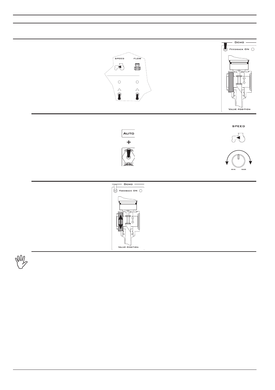
PhAse 1
• Lower the
SPEED
and
FLOW
switches
PhAse 2
• Lift the
FEEDBACK ON
switch
PhAse 3
• On the Bravo computer enable the
section valves.
The LEDs on the computer
(if present) and LED connectors
must get red.
• Enable automatic regulation
function on the Bravo computer, set
output value and start spraying.
PhAse 4
• Use the
SPEED
knob to
regulate the speed of the tractor.
If everything works correctly,
the Bravo display will show the
variation of the values relative to
speed and spraying data.
These latter values will be
automatically corrected by Bravo,
using the regulation valve to
compensate for variations in
speed.
PhAse 5
• On the Bravo DSB it will be pos-
sible to check the behaviour of the
regulation valve through the LED
bar in section
O (Control Panel).
The LEDs on the bar should switch
on and off to simulate opening
and closing of the regulation valve
during the variations in speed of the
tractor.
The system simulates the functioning of the regulation valve when used as a dump
valve, which is its typical application in case of plunger or diaphragm pumps.
When the regulation valve is used as a 2-ways valve (typical application with
centrifugal pumps), the functioning of the LED bar will be inverted.
10