Installation, 4) sensor connection alarm pin define – ARM Electronics NDVR16 User Manual
Page 7
7
Installation
Procedure
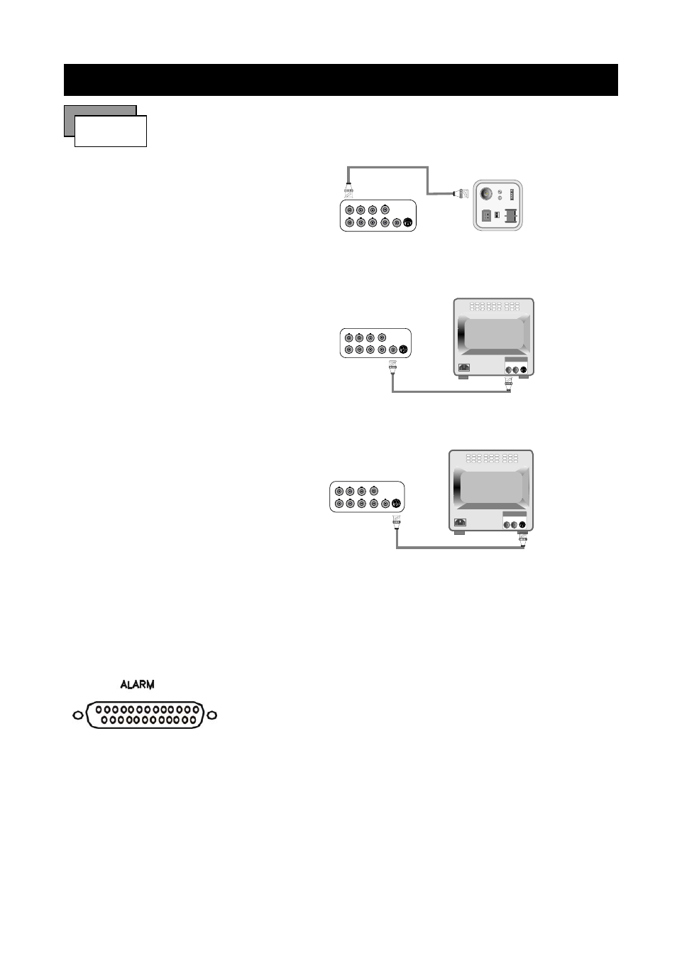
1) Camera Connection
Connect the camera to the CAMERA INPUT
on the Rear Panel of the 16 CH DVR.
CH1
CH2
CH3
CH4
CH1
CH2
CH3
CH4
MONITOR
VIDEO
LENS
VIDEO
DC
AC24V/DC12
V.P
DC
LEVEL
Rear part of CAMERA
2) Monitor Connection (Composite Connection
Method)
Connect the monitor to the MONITOR OUT on
the Rear Panel of the 16 CH DVR.
CH1
CH2
CH3
CH4
CH1
CH2
CH3
CH4
MONITOR
VIDEO A
IN
OUT
3) Monitor (S-VHS) Connection
Connect S-VIDEO Monitor to MONITOR OUT
(S-VHS) on the Rear Panel of the 16 CH DVR.
CH1
CH2
CH3
CH4
CH1
CH2
CH3
CH4
MONITOR
VIDEO A
IN
OUT
4) Sensor Connection
ALARM pin define.
13,12,11,10,9,8,7,6,5,4,3,2,1
25,24,23,22,21,20,19,18,17,16,15,14,13,12,11
1.ALARM0 14. ALARM 13
2.ALARM1 15. ALARM 14
3.ALARM2 16. ALARM 15
4.ALARM3 17. ALARM COMM 2
5.ALARM4 18. DGND
6.ALARM5 19. DGND
7.ALARM6 20. DGND
8.ALARM7 21. ALARM NC 1
9. ALARM8 22. ALARM COMM 1
10.ALARM9 23. ALARM NO 1
11. ALARM10 24.ALARM NC 2
12.ALARM11 25. ALARM NO 2
13. ALARM12