Internal circuit – ARM Electronics NDVR16 User Manual
Page 8
NOTICE: Sensor input is RECOGNIZED as LOW when alarm signal is on a level with GND, and it is
recognized as HIGH when alarm signal is FLOATING or 5V. Following is internal circuit.
D1
5
V
Internal Circuit
Thus, there is a danger of damage, when the sensor input goes to a Negative level or voltage higher than 5V.
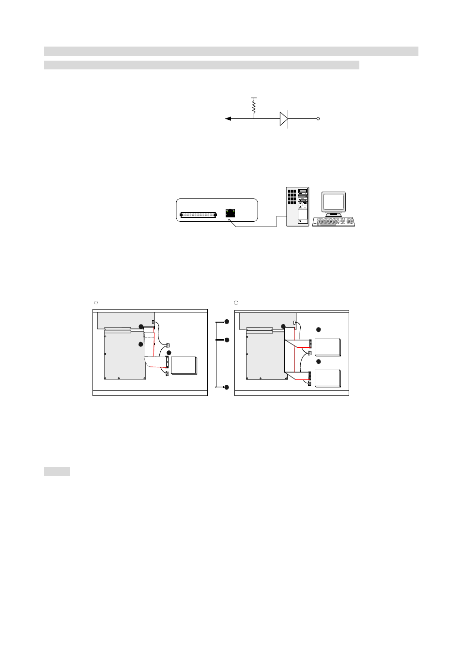
5) Network Connection
8
DVR connects to LAN
rks
TERATRAY CONNECTION
ETHERNET
◆
To view video image on the computer through internet with DVR view software.
6) HDD connection
HDD
MASTER
MAIN BOARD
I/O BOARD
Set the drive jumpers as specified by hard disk drive manufacturer.
1
2
3
1
3
2
tie
HDD1
HDD2
MASTER
SLAVE
MAIN BOARD
I/O BOARD
Set the drive jumpers as specified by hard disk drive manufacturer.
2
1
3
1
How to connect single HDD
2
How to connect 2 HDD
1.
Make sure the HDD is MASTER.
2. Make sure the cable connector is
correct.
3.
MASTER set up, please check the
HDD panel.
1. Make sure the HDD is MASTER and
SLAVE.
2.
Make sure the cable connector is correct.
3. MASTER and SLAVE set up, please check
the HDD panel.
Notice:
-The 16 ch DVR provides 2 internal hard drives. We provide one hard disk drive with removable rack; the
other one is fixed designed.
-We recommend you to set the Removable Hard Disk as Slave. Set the other one as the Master.