Ensemble Designs 6040 Tracking Audio Delay User Manual
Page 12
Internal Switches
When using the 6040 in Local mode, several switches must be set on the circuit board as
detailed in this section.
The following parameters must be set on the circuit board in Local mode:
•
Digital Reference (Internal DIP switch S2, positions 1 and 2)
•
Analog In (Internal DIP switch S2, positions 3 and 4)
•
Analog Out (Internal DIP switch S2, positions 5 and 6)
Refer to the module circuit board layout illustration below to locate each jumper and
switch. The settings for each switch are given in the corresponding tables below.
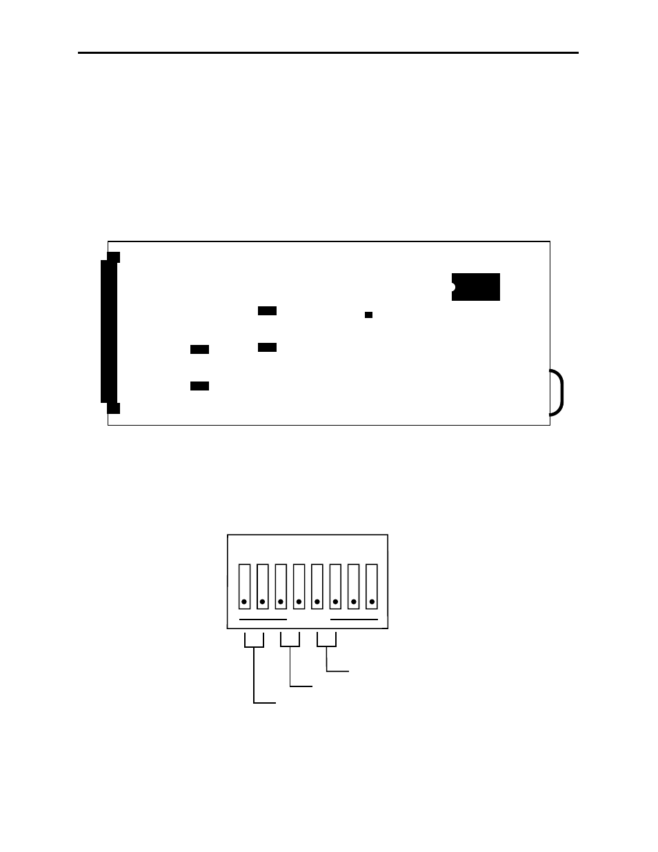
The 6040 uses an eight position DIP switch, S2, for setting various local levels. The switch
function is shown below:
Model 6040 Tracking Audio Delay
J5
J6
J8
J7
S2
D14
6040 Component Side
Internal Jumpers and Switches
1 2 3 4 5 6 7 8
OPEN
Dot on switch represents rocker switch up
Digital Ref (1-2)
Analog In (3-4)
Analog Out (5-6)
DIP Switch S2
6040-12