H3C Technologies H3C S5820X Series Switches User Manual
Page 25
15
Power
module
Specifications Switch
chassis
Reference
PSR300-12D1
PSR300-12D2
•
Rated input voltage range:
–48 VDC to –60 VDC
•
Max input voltage range:
–40.5 VDC to –72 VDC
•
Max output power:
300 W
S5820X-28S
S5820X-28C
H3C PSR300-12A &
PSR300-12D Series Power
Modules User Manual
LSVM1AC650
•
Rated input voltage range:
100 VAC to 240 VAC @ 50 Hz or 60
Hz
•
Max input voltage range:
90 VAC to 264 VAC @ 47 Hz or 63
Hz
•
Max output power:
650 W
S5820X-26S
H3C LSVM1AC650 &
LSVM1DC650 Power
Modules User Manual
LSVM1DC650
•
Rated input voltage range:
–40 VDC to –60 VDC
•
Max input voltage range:
–40 VDC to –72 VDC
•
Max output power:
650 W
S5820X-26S
H3C LSVM1AC650 &
LSVM1DC650 Power
Modules User Manual
LSVM1AC300
•
Rated input voltage range:
100 VAC to 240 VAC @ 50 Hz or 60
Hz
•
Max input voltage range:
85 VAC to 264 VAC @ 47 Hz or 63
Hz
•
Max output power:
315 W
S5820X-26S
H3C LSVM1AC300 &
LSVM1DC300 Power
Modules User Manual
LSVM1DC300
•
Rated input voltage range:
–48 VDC to –60 VDC
•
Max input voltage range:
–36 VDC to –72 VDC
•
Max output power:
315 W
S5820X-26S
H3C LSVM1AC300 &
LSVM1DC300 Power
Modules User Manual
CAUTION:
•
Do not install a 650 W power module (LSVM1AC650 or LSVM1DC650) and a 300 W power module
(LSVM1AC300 or LSVM1DC300) on the same S5820X-26S switch.
•
In power redundancy mode, you can replace a power module without powering off the switch but must
strictly follow the installation and procedures in
to avoid any bodily injury or
damage to the switch.
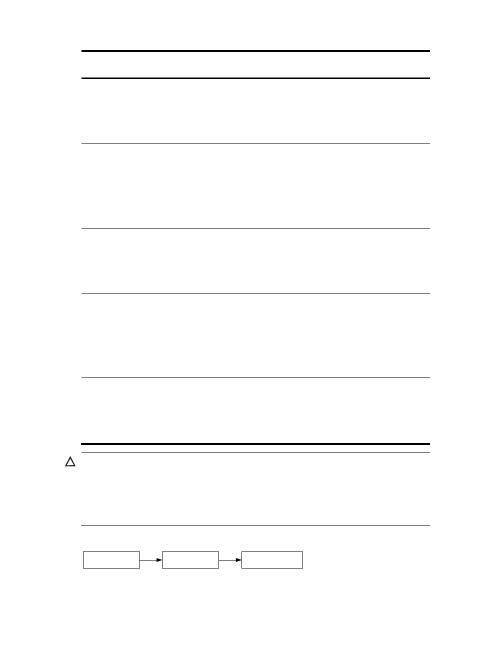
Figure 9 Installation and power-on procedure
Install the
power module
Connect the
power cord
Switch on the
power module
Install the
power module
Connect the
power cord
Switch on the
power module