Planning the cabling scheme – H3C Technologies H3C S5820X Series Switches User Manual
Page 76
66
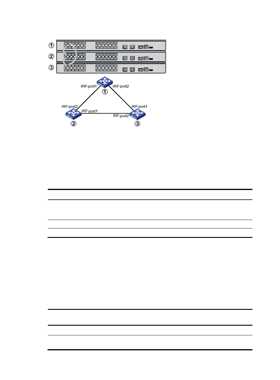
Figure 69 IRF fabric in ring topology
Identifying physical IRF ports on the member switches
Identify the physical IRF ports on the member switches according to your topology and connection
scheme.
shows the physical ports that can be used for IRF connection and the port use restrictions.
Table 26 Physical IRF port requirements
Switch chassis Candidate physical IRF ports
Requirements
S5820X-28C
•
The 14 fixed SFP+ ports on the front panel
•
Ports on the expansion interface cards
An IRF port can use a mix of fixed ports
and ports on an expansion interface
card.
S5820X-28S
The 24 fixed SFP+ ports on the front panel
No special requirements.
S5820X-26S
The 24 fixed SFP+ ports on the front panel
No special requirements.
Planning the cabling scheme
Use SFP+ cables, twisted pair cables, or SFP+ transceivers and fibers to connect the IRF member switches.
If the IRF member switches are far away from one another, choose the SFP+ transceiver modules with
optical fibers. If the IRF member switches are all in one equipment room, choose SFP+ cables or twisted
pair cables.
lists the SFP+ transceiver modules and SFP+ cables available for IRF connections.
Table 27 SFP+ transceiver modules and SFP+ cables available for IRF connections
Transceiver/cable
Central
wavelength
Connector Fiber
Max transmission
distance
10 GE SFP+ transceivers
SFP-XG-SX-MM850-A 850
nm LC
50/125 μm multimode
optical fiber
300 m (984.3 ft.)