Network diagram, Configuration procedure – H3C Technologies H3C S5120 Series Switches User Manual
Page 343
2-6
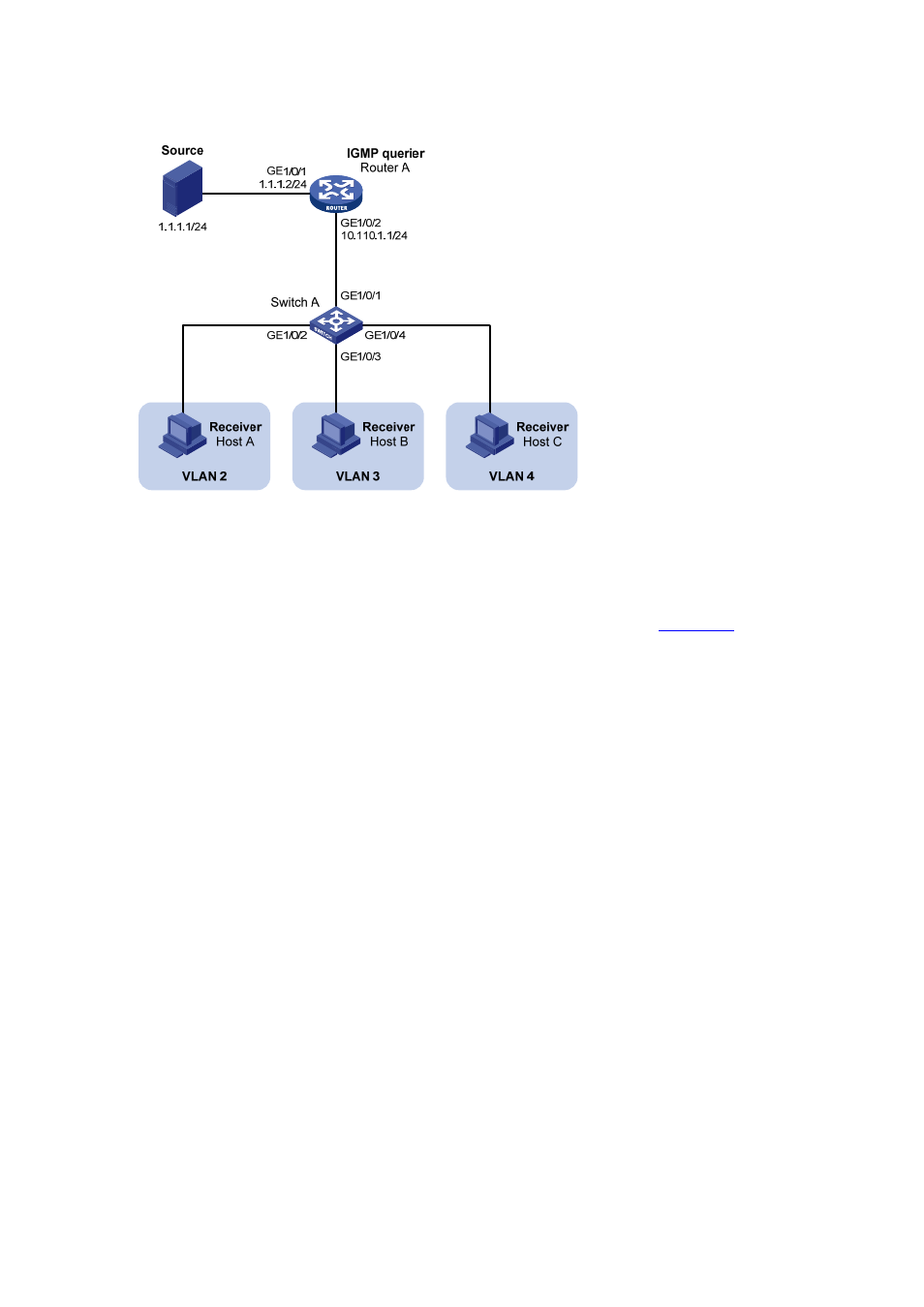
Network diagram
Figure 3-3 Network diagram for port-based multicast VLAN configuration
Configuration procedure
1) Configure
IP
addresses
Configure the IP address and subnet mask for each interface as per
The detailed
configuration steps are omitted here.
2) Configure Router A
# Enable IP multicast routing, enable PIM-DM on each interface, and enable IGMP on the host-side
interface GigabitEthernet 1/0/2.
<RouterA> system-view
[RouterA] multicast routing-enable
[RouterA] interface gigabitethernet 1/0/1
[RouterA-GigabitEthernet1/0/1] pim dm
[RouterA-GigabitEthernet1/0/1] quit
[RouterA] interface gigabitethernet 1/0/2
[RouterA-GigabitEthernet1/0/2] pim dm
[RouterA-GigabitEthernet1/0/2] igmp enable
3) Configure Switch A
# Enable IGMP Snooping globally.
<SwitchA> system-view
[SwitchA] igmp-snooping
[SwitchA-igmp-snooping] quit
# Create VLAN 10, assign GigabitEthernet 1/0/1 to VLAN 10, and enable IGMP Snooping in this VLAN.
[SwitchA] vlan 10
[SwitchA-vlan10] port gigabitethernet 1/0/1
[SwitchA-vlan10] igmp-snooping enable
[SwitchA-vlan10] quit