Grass Valley 7600REF User Manual
Page 22
Advertising
22
7600 SD/HD/MHD-REF — Instruction Manual
Installation
GPI Inputs 1 and 2
The General Purpose Interface (GPI) inputs 1 and 2 are configured in soft-
ware using the menus described in
to provide
any of the following functions:
•
Force freerun mode
•
Force Genlock mode
•
Force external 10MHz lock mode
•
Step through SDI output 1 test patterns
•
Step through SDI output 2 test patterns
•
Step through SDI output 3 test patterns
•
Step through setup memories
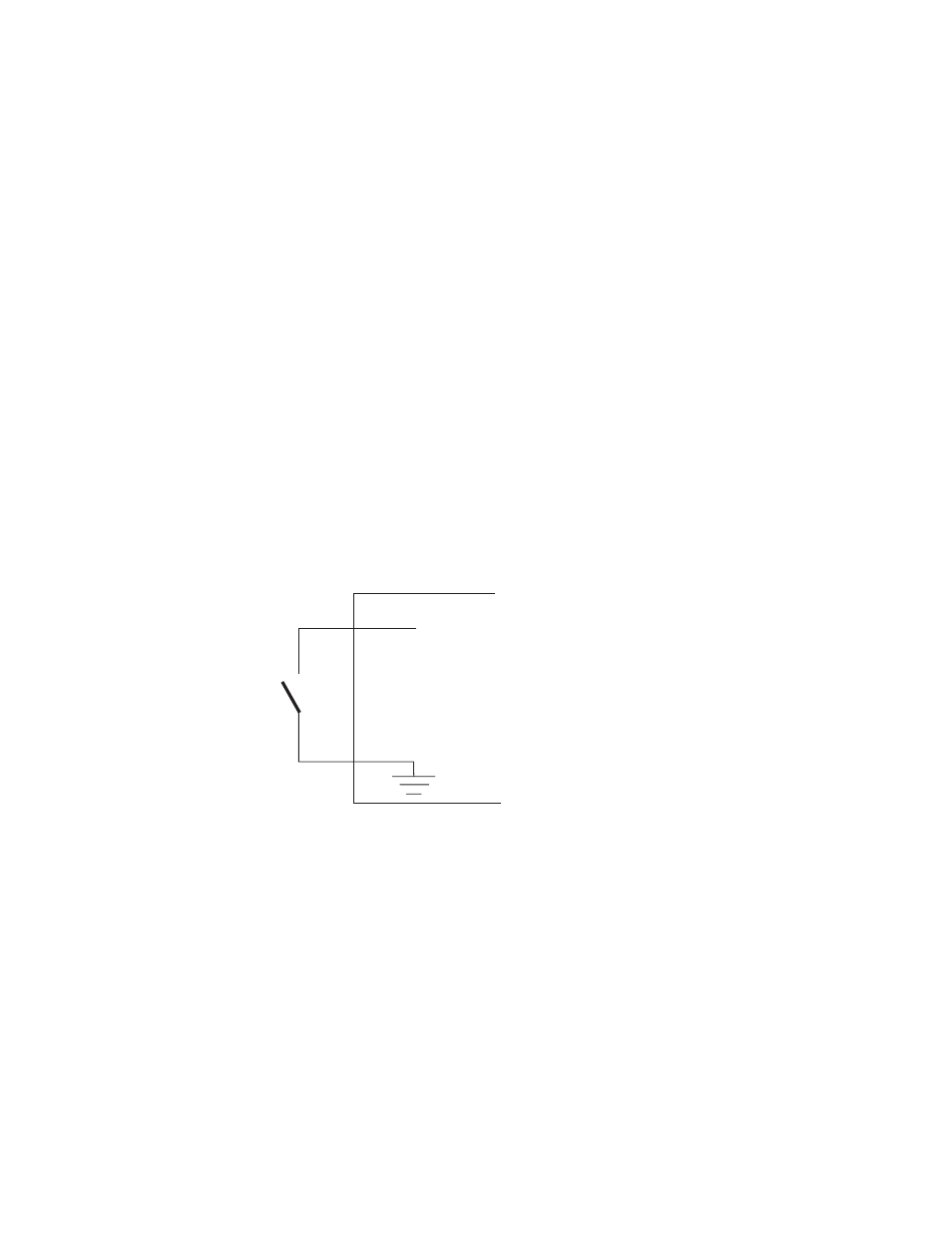
The single-ended 7600 GPI inputs are activated when connected to a
ground connection on the 25 pin Sub-D connector as shown in
.
The two GPI inputs are pin 18 and pin 19 as listed in
inputs can withstand +/- 20V and draw approximately 600uA when acti-
vated.
Figure 2. Connection to GPI Inputs
GPI In
7600Ref
Advertising