Base station camera remote connector – Grass Valley 3430AP CopperHead User Manual
Page 72
60
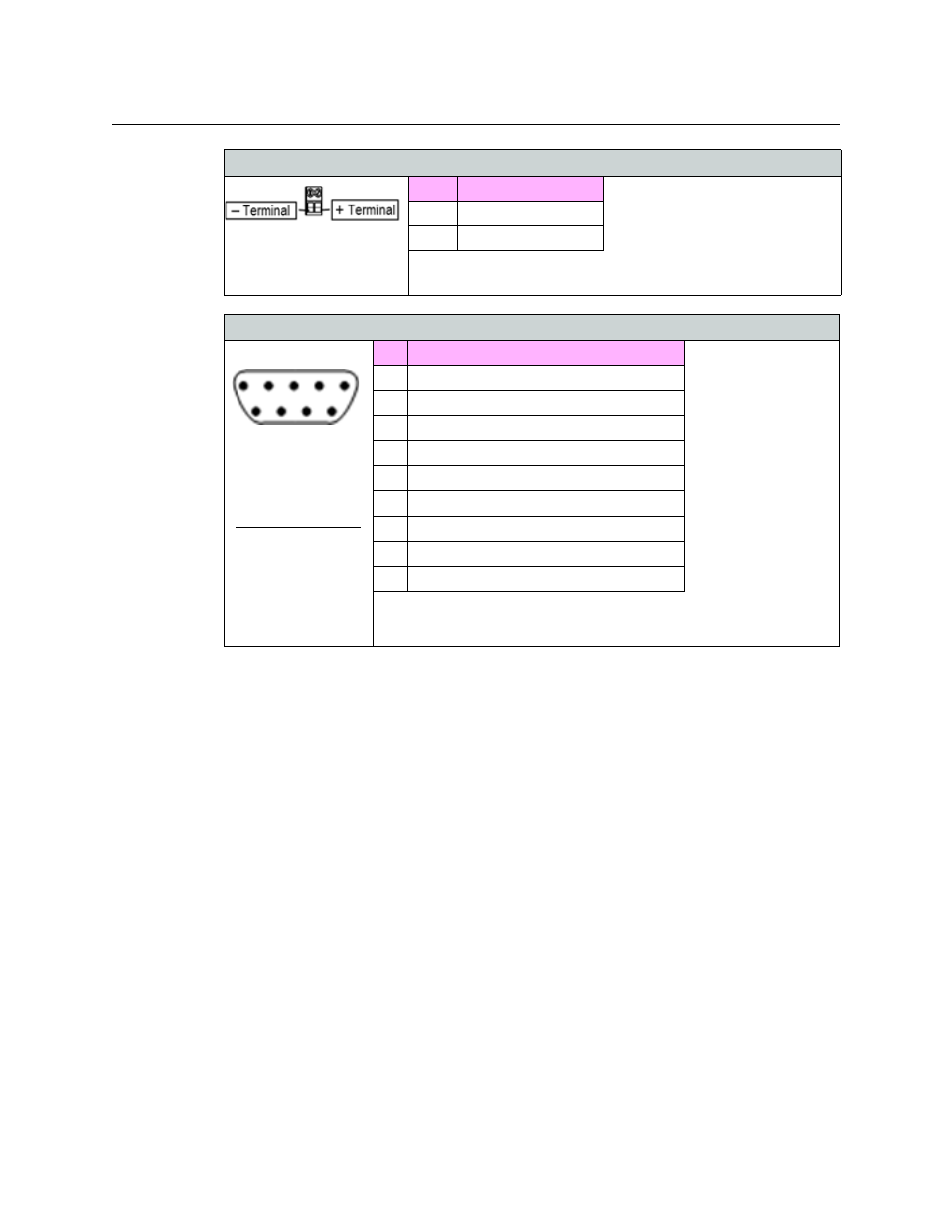
Base Station #21
Terminal Block
Pin
Signal
1
Minus Voltage terminal
2
Plus Voltage terminal
Base Station 12 VDC Terminbal Block wiring
This connector is wired in parallel with XLR4 male # 20 (above)
Base Station Camera Remote Connector
Base Station #9
DB9 Female
Format select (Pin 2)
Floating for RS-422 or
TTL
Tie to GND (pin 3) for
RS-232
Tie to +12VDC (pin 4)
for RS-485
Pin Function
1
Data 1 -422 In, -485 I/O
2
Data 1 Format Select (see choices to the left)
3
GND (Ground)
4
+12 VDC Bias for Data 1 Format Select
5
Data 1 -422 out
6
Data 1 232 In, +422 IN, +485 I/O
7
- 12 VDC Camera Control Data Power Ground
8
+12 VDC Camera Control Data Power
9
Data 1 232 Out, +422 Out
Base Station Camera Remote Connector Wiring
Please see Appendix XX for a list of Miranda-supplied cables.
12VDC Input Power Connectors - Models CHG3-BS-3400-2ST / 2MX / NEU