Grass Valley JEP-100 v.1.2.0 User Manual
Page 62
Advertising
60
JEP-100 — Installation and Operating Manual
Section 1 — JEP-100 Control Panel
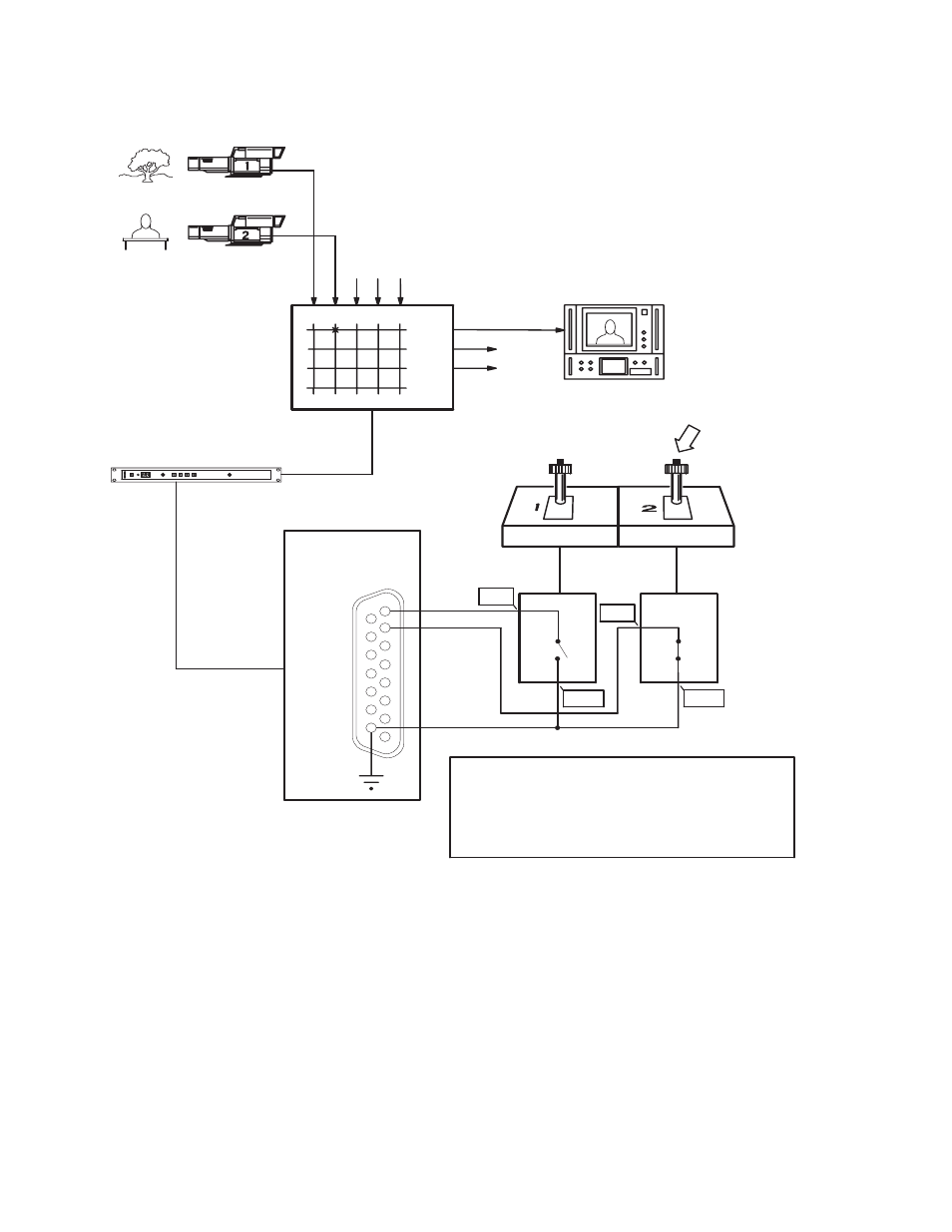
Figure 22. JEP-100 joystick override application
C1
C2
1
2
3
4
5
6
7
8
TAKE
JEP-100
Control Panel
Grass Valley
Crosspoint
Bus Router
CM 4000 Control System
Crosspoint Bus
CCU
Joysticks
Serial or LAN
connection
QC monitors
Joystick Port
CCU
GPO ports
Video sources
9
10
11
12
13
14
15
*
Grass Valley camera connections Grass Valley CCU (base
station) models LDK-4053 through LDK-4502 include a
rear-panel 9-pin D connector labelled “Sign” (Signalling). Pin 1 of
this connector is designated “Preview Out External” and
corresponds to the signals marked “POE” in this drawing. Pin 9 is
designated “Preview Out External Return” and corresponds to the
signals marked “POER.”
POE*
POE*
POER*
POER*
8536_23
Advertising