Grass Valley Maestro Master Control v.1.7 User Manual
Page 115
Maestro Channel Branding User Guide
111
1st Step: Connections
Switch Frame Delay
(Required entry) - Enter the control system switch latency in frames. The
following are default values.
Encore - 12.
Jupiter CM-4000/AccuSwitch - 2
Jupiter CM-4000/JupiterXPress - 4
Jupiter VM-3000 - 6
Note
These values are system-dependent. The above defaults are suggested in
advance of empirical testing using specific systems under defined condi-
tions.
ES-Control RCS Device Name
Encore - no entry.
Jupiter - Select the name of the appropriate configuration set to be used
with Maestro. The source of these names is the Jupiter MPK Devices table.
If you do not see the names expected on the drop-down list, it may be that
the connection to the control system server has not been established. By
selecting “Connect to Server” the editor will retrieve configuration data
already entered on the router control system.
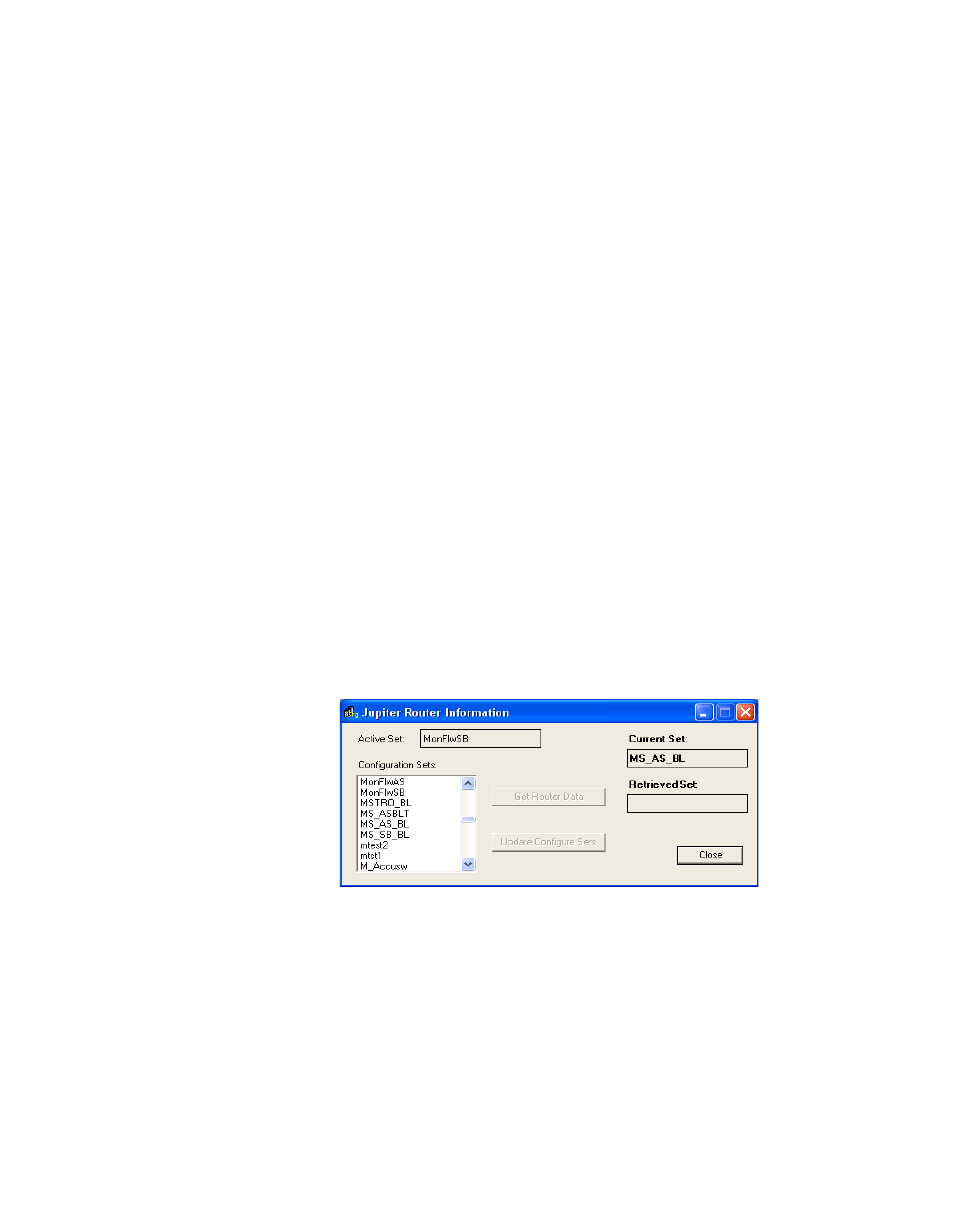
For example, if the router control system is Jupiter, a screen similar to the
following screen will appear:
Figure 86. Jupiter Router Information (Example)
Note
On the Connect to Server menu, the “Active” set field indicates the active set
on the Jupiter system. “Current Set” refers to the active Jupiter configuration
file that is being used with the Maestro configuration currently being edited.
When finished, Click the
Apply
button, and then the
OK
button to save.
Note
After all the configuration tables are edited and saved you must “compile” the
set before it can be downloaded using the Deployment Control Center. This
process is described in