Teleport 3g front panel features, Power and display panel, Teleport 3g transmitter – Grass Valley TelePort 3G User Manual
Page 18
14
TelePort 3G Components
TelePort 3G Front Panel Features
TelePort 3G Front Panel Features
The TelePort 3G is used as a set of two units. The inputs to one unit of the pair are received
by the second unit and appear as the corresponding outputs.
Unit One Inputs 1-8 and 9-16 are reflected on Unit Two as Outputs 1-8 and 9-16.
Transceivers work identically in either direction with Inputs 1-8 reflected as Outputs 1-8 on
the opposite unit.
There is no requirement that all connectors be active. For example, fiber Inputs 1 and 3 are
used, while Input 2 is skipped, the output on the opposite unit will be on Output 1 and 3.
The TelePort 3G provides no user accessible adjustments. The unit is a pass-through device
with selectable monitoring capability.
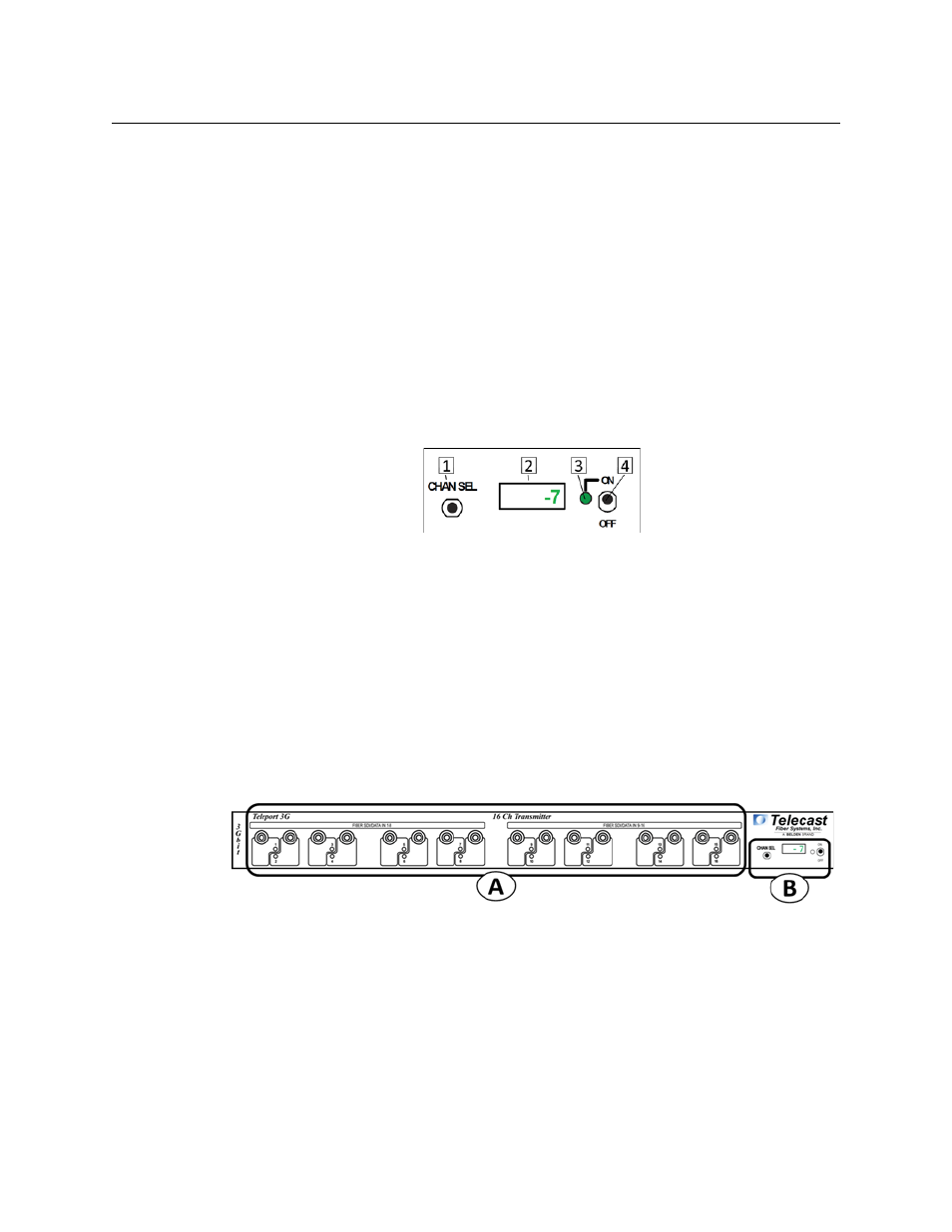
Power and Display Panel
Fig. 3-1: Power and Display features
The Power and Display Area has four features:
• CHAN SEL – scrolls the LED display through each of the Fiber Channels
• Digital Display – display optical power levels, unit firmware and operating temperature
• Power Monitor LED – indicates Power Status
• Red: standby (power applied to rear connectors but unit not switched on)
• Green: unit switched on
• On/Off Switch – controls power to the TelePort 3G unit
TelePort 3G Transmitter
Fig. 3-2: TelePort 3G Transmitter Front Panel
The TelePort 3G Transmitter Front Panel has two features:
• A - SDI/Data In - see