Teleport 3g transceiver, Area a – sdi/data in area b – sdi/data out – Grass Valley TelePort 3G User Manual
Page 20
16
TelePort 3G Components
TelePort 3G Transceiver
TelePort 3G Transceiver
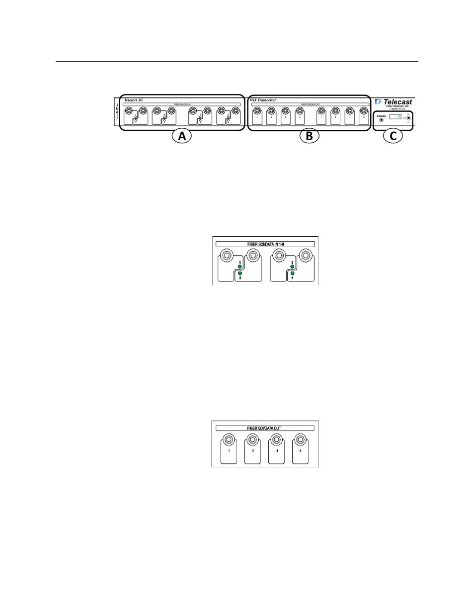
Fig. 3-6: TelePort 3G Transceiver Front Panel
The TelePort 3G Transceiver Front Panel has three features:
• A - SDI/Data In - see
• C - Power & Display Area - see
Area A – SDI/DATA IN
Fig. 3-7: 4 SDI/DATA In BNC Connectors
The TelePort 3G Transceiver has eight Fiber Channel SDI/DATA Input ST connectors on the
front panel. All inputs operate identically and are multiplexed for transmission on the fiber
output of the unit. The Fiber signals are demultiplexed in the receiving unit and appear on
the corresponding ST outputs.
The Fiber connections can carry a digital optical signal of not more than 3 Gb/s.
Each front panel Fiber input has an LED monitor that indicates the following:
• Green: fiber optic connection present with active SDI signal
• Red: no optical connection is detected or the active optical signal is below -22 dBm
Area B – SDI/DATA OUT
Fig. 3-8: 4 SDI/DATA Output BNC Connectors
The TelePort 3G Transceiver has eight Fiber Channel SDI/DATA Output ST connectors on the
front panel. All Outputs operate identically and are demultiplexed from the signals received
from the sending unit.
• The Fiber connections can carry a digital optical signal of not more than 3 Gb/s
• The Fiber outputs do not have associated LED indicators