Area b – can bus connector, Area c – the st fiber connectors, Power connector wiring – Grass Valley TelePort 3G User Manual
Page 22
18
TelePort 3G Components
Area B – CAN BUS Connector
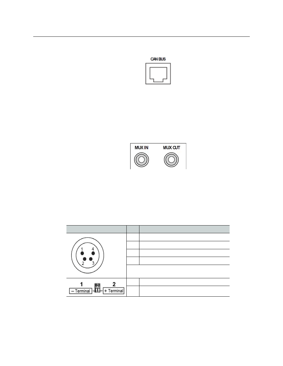
Area B – CAN BUS Connector
Fig. 3-11: CAN BUS connector
The CAN BUS connector is inactive in this version of the TelePort 3G. It may be used for
system monitoring in the future.
CAN is(Communication Area Network) is a protocol designed to support the monitoring of
microcontrollers.
Area C – The ST Fiber Connectors
Fig. 3-12:
MUX IN and OUT connectors
The MUX IN connector receives up to eight or 16 channels depending on whether the unit
is a Tranceiver or Receiver.
Conversely the Transceiver or Transmitter MUX OUT connector sends the up to eight or 16
channels to the opposite TelePort 3G.
Power Connector Wiring
Figure
Pin
Function
1
Ground
2
Unused
3
Unused
4
+ Power 12 VDC
This matching connector is from either an ADAP-AC
04 or a customer 12-18 VDC power supply
1
Minus Voltage Terminal
2
Plus Voltage Terminal