Rs-422/v.11 interface, Ethernet interface rj45 socket – HEIDENHAIN iTNC 530 (340 49x-06) ISO programming User Manual
Page 601
HEIDENHAIN iTNC 530
601
1
8
.2 Pin La
y
outs and Connecting Cables f
or the D
a
ta Int
e
rf
aces
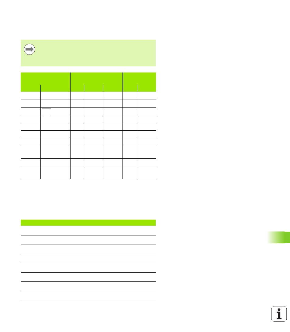
RS-422/V.11 interface
Only non-HEIDENHAIN devices are connected to the RS-422
interface.
Ethernet interface RJ45 socket
Maximum cable length:
Unshielded: 100 m
Shielded: 400 m
The interface complies with the requirements of
EN 50 178 for “low voltage electrical separation.”
The pin layouts on the TNC logic unit (X28) and on the
adapter block are identical.
TNC
Connecting cable
355 484-xx
Adapter block
363 987-01
Female
Pin layout
Male Color
Female
Male
Female
1
RTS
1
Red
1
1
1
2
DTR
2
Yellow
2
2
2
3
RXD
3
White
3
3
3
4
TXD
4
Brown
4
4
4
5
Signal GND
5
Black
5
5
5
6
CTS
6
Violet
6
6
6
7
DSR
7
Gray
7
7
7
8
RXD
8
White/
Green
8
8
8
9
TXD
9
Green
9
9
9
Hsg.
Ext. shield
Hsg.
External
shield
Hsg.
Hsg.
Hsg.
Pin
Signal
Description
1
TX+
Transmit Data
2
TX–
Transmit Data
3
REC+
Receive Data
4
Vacant
5
Vacant
6
REC–
Receive Data
7
Vacant
8
Vacant