Ik 5000 quadra-chek connector pin assignments – HEIDENHAIN IK 5294 Installation User Manual
Page 95
95
IK 5000 QUADRA-CHEK
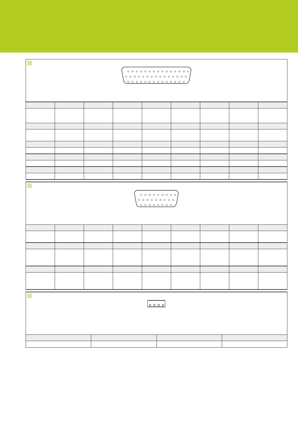
Connector pin assignments
A
X, Y, Z, Footswitch
1
2
3
4
5
6
7
8
9
X, 0° +
X, 90° +
X, Ref mark
+
X, DC -12 V
Y, 0° -
Y, 90° -
Y, Ref mark -
Y, Reset
Y, DC +12 V
10
11
12
13
14
15
16
17
18
Z, 0° +
Z, 90° +
Z, Ref mark
+
Z, DC -12 V
Z, GND
Footswitch 2
X, 0° -
X, 90° -
X, Ref mark -
19
20
21
22
23
24
25
26
27
X, Reset
X, DC +12 V
Y, 0° +
Y, 90° +
Y, Ref mark +
Y, DC -12 V
Z, 0° -
Z, 90° -
Z, Ref mark -
28
29
30
31
32
33
34
35
36
Z, Reset
Z, DC +12 V Footswitch 1
X, DC +5 V
X, LED +
X, DC -5 V
X, LED -
X, GND
Y, DC +5 V
37
38
39
40
41
42
43
44
-
Y, LED +
Y, DC -5 V
Y, LED -
Y, GND
Z, DC +5 V
Z, LED +
Z, DC -5 V
Z, LED -
/
B
X, Y, Z CNC
1
2
3
4
5
6
7
8
9
X motor - or
X direction
Y motor - or
Y direction
Z motor - or
Z direction
Y joystick in
DC 0 ... 5 V
Joystick
DC +12 V
Button 2
TTL in
X positioner
90 °
Y positioner
90 °
Z positioner
90 °
10
11
12
13
14
15
16
17
18
X motor +
drive servo/
stepper
Y motor +
drive servo/
stepper
Z motor +
drive servo/
stepper
X joystick in
DC 0 ... 5 V
Z joystick in
DC 0 ... 5 V
Button 1
TTL in
X positioner
0 °
Y positioner
0 °
Z positioner
0 °
19
20
21
22
23
24
25
26
-
Amp inhibit
TTL out
CNC loop
mode TTL
out
Motor GND Joystick GND
Joystick
DC +5 V
Button 3
TTL in
Positioner
DC +5 V
Positioner
GND
E
PC internal power
1
2
3
4
DC +5 V
GND
GND
DC +12 V
1
2
3
4
5
6
7
10
11
12
13
14
15
9 8
16
17
18
19
20
21
22
25
26
27
28
29
30
24 23
31
32
33
34
35
36
37
40
41
42
43
44
39 38
1
2
3
4
5
6
7
9 8
10
11
12
13
14
15
16
18 17
26
25
24
23
22
21
20
19
1
2
3
4