1 connection area, 2 leading the cables into the interface cabinet – SMA SC 500CP-10-JP Installation Manual User Manual
Page 58
12 Cable Connection of External Devices and Connections in the Interface Cabinet
SMA Solar Technology AG
58
SCCP-JP-IA-A4-en-12
Installation Manual
12 Cable Connection of External Devices and Connections in the Interface
Cabinet
The connection of external devices depends on the project configuration. You must select the relevant section. Note that
for unused functions such as remote shutdown or transformer protection, the parameter settings must be checked and
changed, if necessary.
12.1 Connection Area
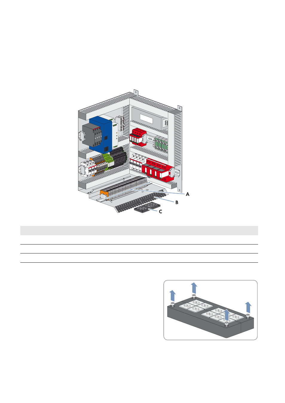
Figure 26: Terminals in the interface cabinet
12.2 Leading the Cables into the Interface Cabinet
1. Remove the four screws at the top of the sealing plate.
2. Remove the sealing plate.
Position
Designation
A
Customer connection terminals
B
Cable support rail
C
Sealing plate with rubber seals (diameter: 6 mm to 7 mm)