6 installing the splice box, Installing the splice box – SMA String-Monitors Optical Fiber Interface Module User Manual
Page 25
4.6
Installing the Splice Box
The splice box is delivered with one cable gland pre-mounted for one optical fiber. If you need two
cable glands, you must mount one more cable gland to the splice box.
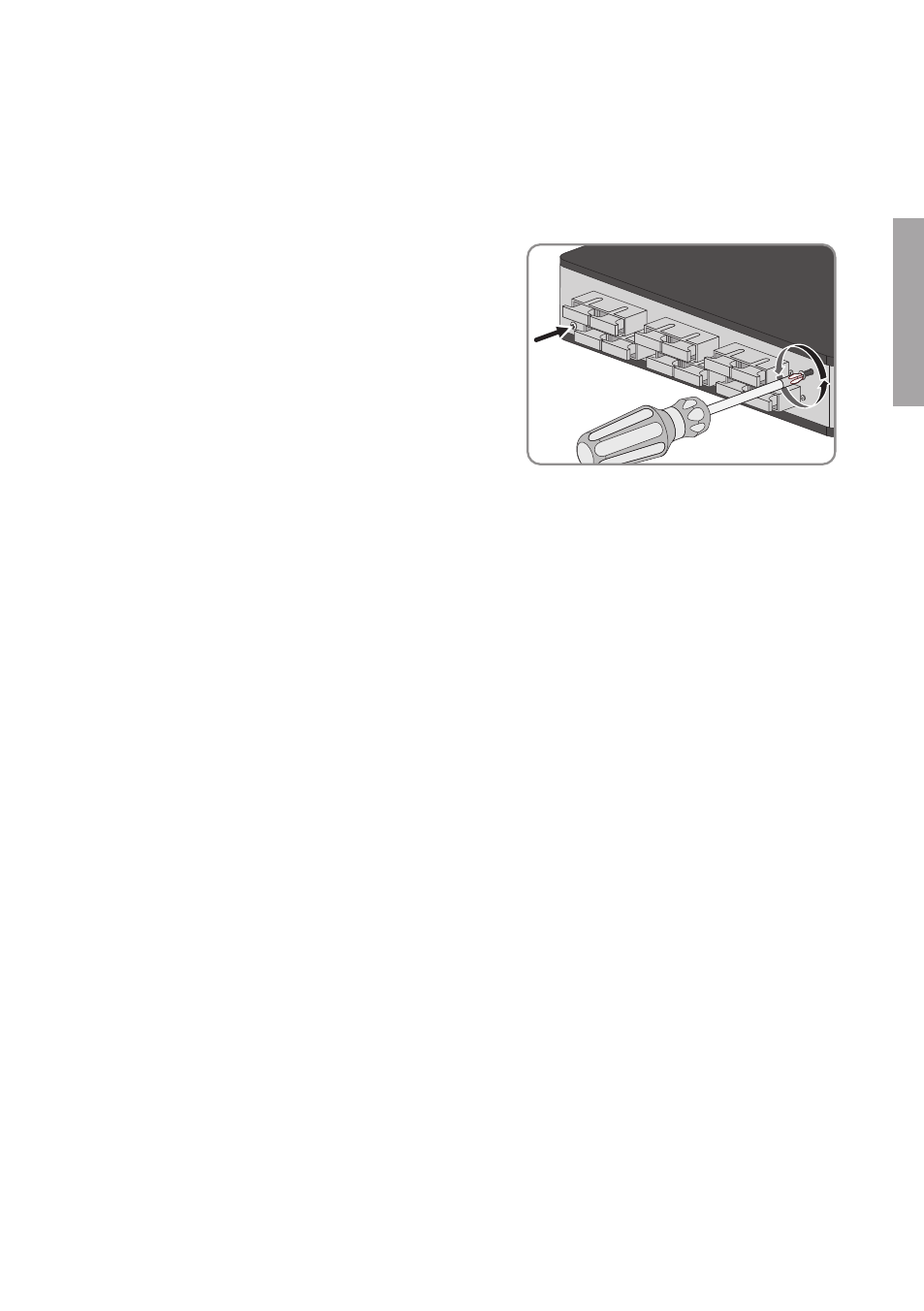
Mounting Two Cable Glands on the Splice Box
1. Loosen the two outer screws on the front side.
There is no need to remove the screws as they
are being held by plastic washers.
2. Remove the gray insert.
3. Unscrew both filler plugs and the cable gland.
4. Mount the enclosed cable gland and the previously removed cable gland on the same side.
5. Mount one filler plug on the opposite side. This will ensure that no moisture or dirt can
penetrate the enclosure.
6. If the splice box is to be installed at a later time, insert the gray insert and screw it tight.
Installing the Splice Box in the DC Subdistribution
Optical fiber requirements in multi mode:
☐ 50/125 µm
☐ Category: OM2
☐ Plug: SC MMF
Requirements:
☐ The DC subdistribution and the inverter must be disconnected.
☐ The optical fibers must be laid in the DC subdistribution.
Additionally required mounting material (not included in the scope of delivery):
☐ One or two optical fiber pigtails in accordance with the specifications of the optical fiber
or
☐ One or two SC duplex connector(s)
Procedure:
1. Clamp the splice box onto the top-hat rail in accordance with the mounting position (see
Section 4.3 "Mounting Position and Cable Route", page 23).
2. Clamp the end clamp flush above the splice box onto the top-hat rail.
☑ The end clamp audibly clicks into place and the splice box can no longer be moved on
the top-hat rail.
4 Installation
SMA Solar Technology AG
Installation Manual
25
SSMLWL-IA-xx-10
ENGLISH