SMA Sunny Boy Control User Manual
Page 34
Advertising
Sunny Boy Control
SMA Technologie AG
User Manual
SUNBC-14:NE0206
30
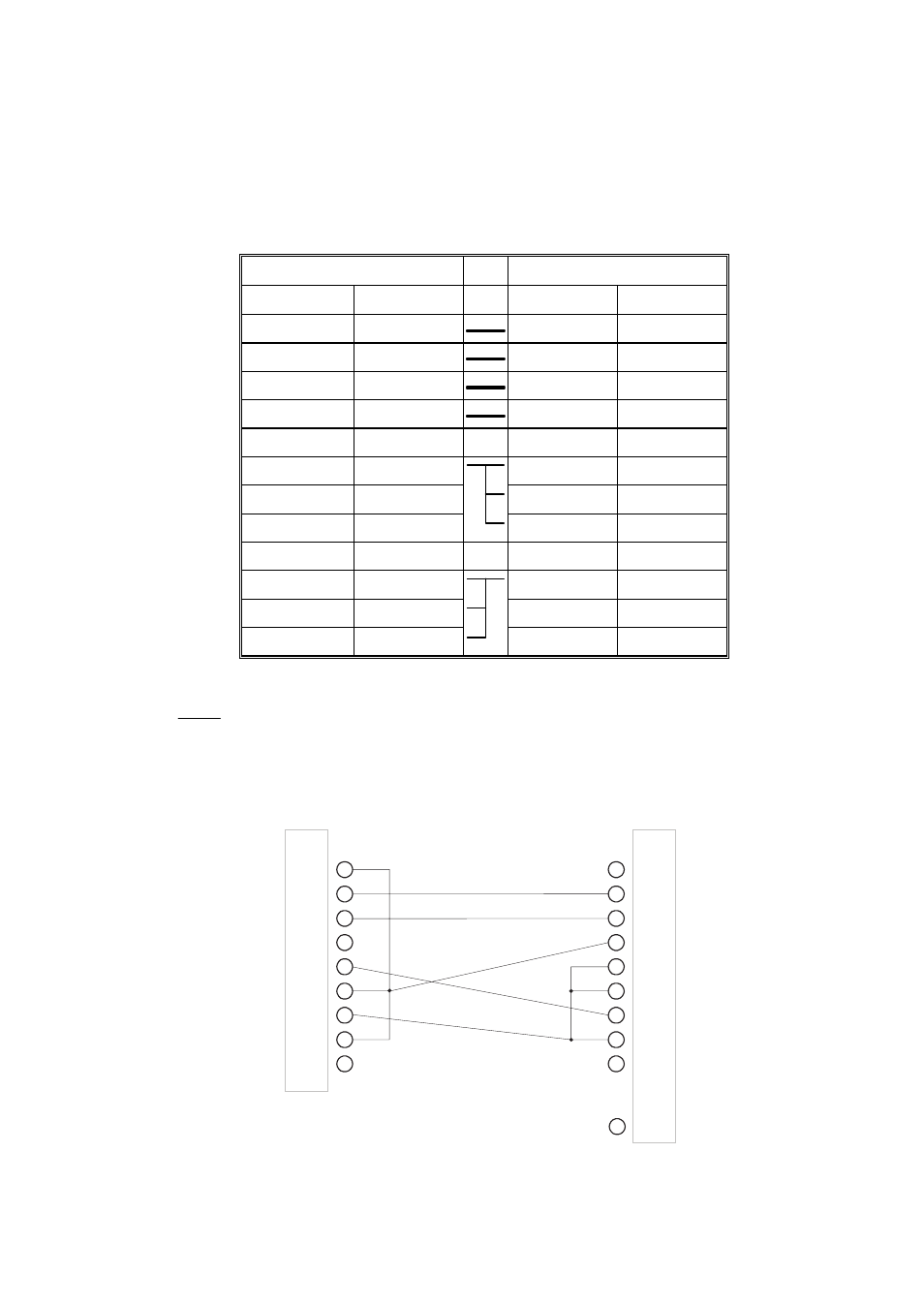
Pin assignment of a DB9-DB25 cable for a PC-to-Sunny Boy Control
connection
DB9 plug
DB25 plug
Signal Pin Pin Signal
/TXD 3
3 /RXD
/RXD 2
2 /TXD
/TXD 3
3 /RXD
GND 5
7 GND
RTS 7
5 CTS
6
DSR
8 DCD
CTS 8
4 RTS
DCD 1
DSR 6
Table 3.4: Pin assignment of a DB9-DB25 cable for PC connection
: These pins are connected together.
Pins 1, 6, and 8 of the DB9 plug as well as pins 5, 6, and 8 of the DB25 plug
are bridged.
PIN
1
2
3
4
5
6
7
8
9
PIN
1
2
3
4
5
6
7
8
9
DB9 socket
DB25 socket
25
.
.
.
Fig. 3.12: Diagram of DB9-DB25 cable for PC connection
Advertising
This manual is related to the following products: