5 installation procedure – Yaskawa 1000 Series Drive Option - Digital Output Installation User Manual
Page 18
5 Installation Procedure
18
YASKAWA ELECTRIC TOBP C730600 41F 1000-Series Option DO-A3 Installation Manual
5.
Wire the customer-supplied circuit to the terminal blocks on the option. Refer to
for wiring instructions.
Connection Diagram
Refer to
on page
for a detailed description of the option board terminal
functions. To ensure accurate control, use stable power supply for the voltage
reference source.
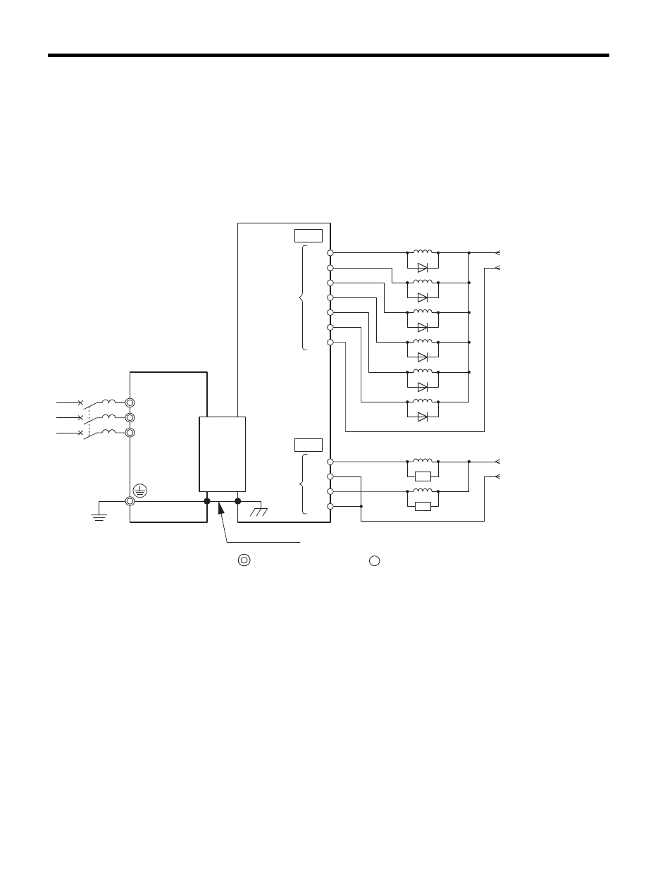
Figure 8
Figure 8 Option Connection Diagram
<1> Double-check the polarity on the diode when connecting a DC relay.
<2> Install a surge absorber (SA) when using an AC relay.
Ground wire
CN5-A/
CN5-B/
CN5-C
Unit
DO-A3
TB2
TB1
RLY1
RLY2
RLY3
RLY4
RLY5
RLY6
P1
P2
P4
P3
P5
P6
PC
M1
M2
M4
M3
RLY7
SA
RLY8
SA
DC power supply
(48 V, max.50 mA)
Photocoupler
output
Relay output
AC power supply
(AC250 V, max.1 A)
or
DC power supply
(30 V, max.1 A)
R/L1
S/L2
T/L3
<1>
<2>
FE
Main circuit terminal
Control circuit terminal
DO