Yaskawa DI-16H2 User Manual
Page 3
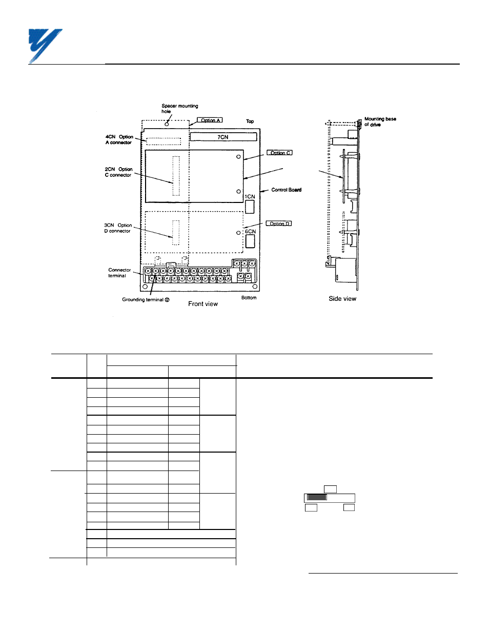
Figure 2. Installation of Digital Reference Card (DI-16H2) in GPD 515/G5
Table 3. Terminal Functions of DI-16H2
Terminal Pin
Function
Block
No.
Binary Input
BCD Input
Notes
1
2
0
1
2
2
1
2
— "On" when closed (shorted to 0V at TC2-9);
3
2
2
4
x 10
0
"Off" when open.
TC1
4
2
3
8
5
2
4
1
— Binary / BCD selection and input unit is set by
6
2
5
2
GPD 515/G5 parameter F3-01; see Table 4.
7
2
6
4
x 10
1
8
2
7
8
— Terminal screws are metric size M3.
9
2
8
1
10
2
9
2
— Set selection switch S1 according to the input signal
1
2
10
4
x 10
2
configuration being used:
2
2
11
8
S1
3
2
12
1
4
2
13
2
16
12
TC2
5
2
14
4
x 10
3
Binary 16 bits/BCD 4 digits Binary 12 bits/BCD 3 digits
6
2
15
8
7
SIGN signal
— SIGN signal: "Off" = Forward direction command
8
SET (read) signal *
"On" = Reverse direction command
9
Frequency Ref. Common (0V)
TC3
Shield sheath connection
DI-16H2
* SET (read) signal is the signal to read digital speed refenerce data. When
reading, close between TC2-8 and TC2-9 by the timing shown in Figure 4.
Yaskawa Electric America, Inc-www.drives.com
02Y00025-0400 Page 3 OF 5
REL. 05/21/96
DIGITAL REFERENCE CARD
(DI-16H2) MODEL DS016