Yaskawa DI-16H2 User Manual
Page 5
IMPORTANT
The DI-16H2 input circuits can receive output of relay contacts or transistor (open collector).
– Use relays with highly reliable contacts (for very small current) with a capacity of 30VDC or more and rated
current of 100mA or higher.
– Use transistor (open collector) with rated voltage of 35VDC or more and rated current of 30mA or higher.
7. Adjustments. There are no adjustments to be made on the Digital Speed Reference option; however, the GPD
515/G5 will have to be reprogrammed for the input requirement of the digital reference. See Table 4, and refer to the
Technical Manual description of parameter b1-01 (Reference Selection).
IMPORTANT
For the Digital Reference circuit to function properly, GPD 515/G5 parameter b1-01 must be set to " 3 " (input to DI-
16H2 replaces auto speed reference signal).
8. Reinstall and secure drive cover.
9. Place this instruction sheet with the GPD 515/G5 technical manual.
THIS COMPLETES INSTALLATION OF THIS OPTION.
Table 4. F3-01 – Setting Unit and Range
F3-01 Set Value
Setting Unit
Setting Range
0
BCD
1%
0 - 159 %
1
BCD
0.1%
0.0 - 15.9 %
2
BCD
0.01%
0.00 - 1.59 %
3
BCD
1Hz
0 - 159 Hz
4
BCD
0.1Hz
0.0 - 15.9 Hz
5 or 6
BCD
0.01Hz
0.00 - 1.59 Hz
7
Binary
255/100%
0 - Max. Output Freq.
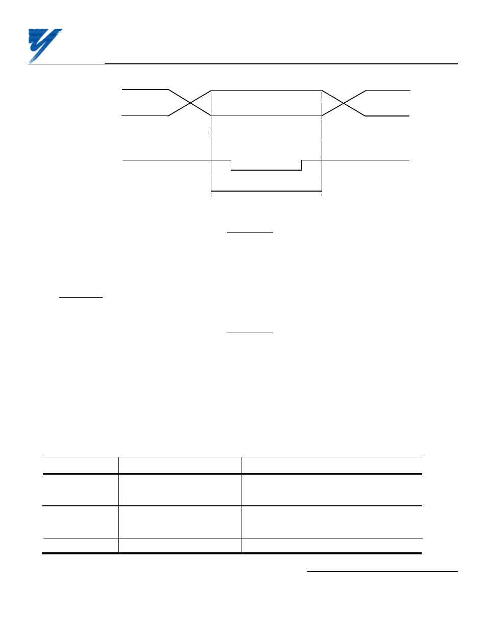
Figure 4. Timing of Reference Input
Digital Reference Data
(Terminals TC1-1 to -10,
TC2-1 to -6, and SIGN
signal, Terminal TC2-7)
SET (read) signal
(Terminal TC2-8)
More
than
5ms
More
than
5ms
More than 40ms
Yaskawa Electric America, Inc-www.drives.com
02Y00025-0400 Page 5 OF 5
REL. 05/21/96
DIGITAL REFERENCE CARD
(DI-16H2) MODEL DS016