Yaskawa DS388 User Manual
Page 4
Refer to Sheet 1 for latest change.
6. Adjustments. There are no adjustments to be made on the Digital Speed Reference option; however, the
drive will have to be reprogrammed for the input requirement of the digital reference. If this option is being installed
in a GPD 515, see Table 3. If this option is being installed in a GPD 503, see Table 4.
DWG. NO. 02Y00025-0294
SHEET NO. 4 OF 6
R E L . 0 1 / 2 9 / 9 1
( m - df )
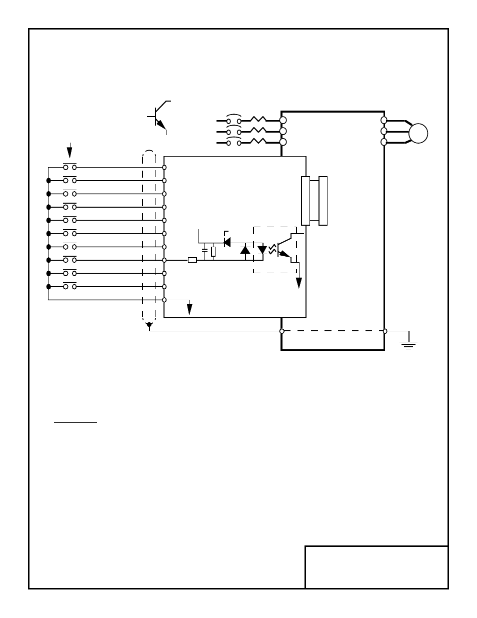
Figure 3. Interconnection for Digital Speed Reference (DI-08) Circuit
2CN
2CN
TC1
12
GPD 515
or
GPD 503
DI-08 BOARD
L1
L2
L3
T1
T2
T3
E
D0
TRANSISTOR
OPEN COLLECTOR
OUTPUT MAY BE
USED IN PLACE OF
RELAY CONTACT
0.1uF
24K ohm
+24V
5.1K ohm
0V
6.2V
OPTICAL
ISOLATOR
I M
MOTOR
MCCB
SHIELD
OV
TYPICAL INPUT
CIRCUIT
SIGN
D1
D2
D3
D4
D5
D6
D7
PUSH-TO-LOAD
TC10
TC2
TC3
TC4
TC5
TC6
TC7
TC8
TC9
TC11
Route wires from the drive and connect to the peripheral device(s). Refer to "Electrical Installation" in the drive’s
technical manual for further information on use of shielded cable.