Yaskawa 303 Dynamic Braking User Manual
Page 2
DWG. NO. 02Y00025-0299
SHEET NO. 2 OF 6
EFF. 4/24/91
(m-df )
Refer to Sheet 1 for latest change.
Table 1
Drive
Braking Resistor Unit
Voltage
HP(CT)
Part Number
H
W
D
H1
W1
Mtg Screws
1
5P41-0742
13.00
12.00
5.00
9.0
11.00
3/4 (4)
2
2
5P41-0743
13.00
12.00
5.00
9.0
11.00
3/4 (4)
3
3
5P41-0744
13.00
12.00
5.00
9.0
11.00
3/4 (4)
5
5P41-0745
13.00
12.00
5.00
9.0
11.00
3/4 (4)
0
7.5
5P41-0746
13.00
12.00
5.00
9.0
11.00
3/4 (4)
10
5P41-0747
13.00
12.00
5.00
9.0
11.00
3/4 (4)
1
5P41-0752
13.00
12.00
5.00
9.0
11.00
3/4 (4)
4
2
5P41-0753
13.00
12.00
5.00
9.0
11.00
3/4 (4)
6
3
5P41-0754
13.00
12.00
5.00
9.0
11.00
3/4 (4)
5
5P41-0755
13.00
12.00
5.00
9.0
11.00
3/4 (4)
0
7.5 *
5P41-0756
13.00
12.00
5.00
9.0
11.00
3/4 (4)
10
5P41-0757
13.00
12.00
5.00
9.0
11.00
3/4 (4)
15
5P41-0758
13.00
12.00
5.00
9.0
11.00
3/4 (4)
20
5P41-0759
13.00
12.00
5.00
9.0
11.00
3/4 (4)
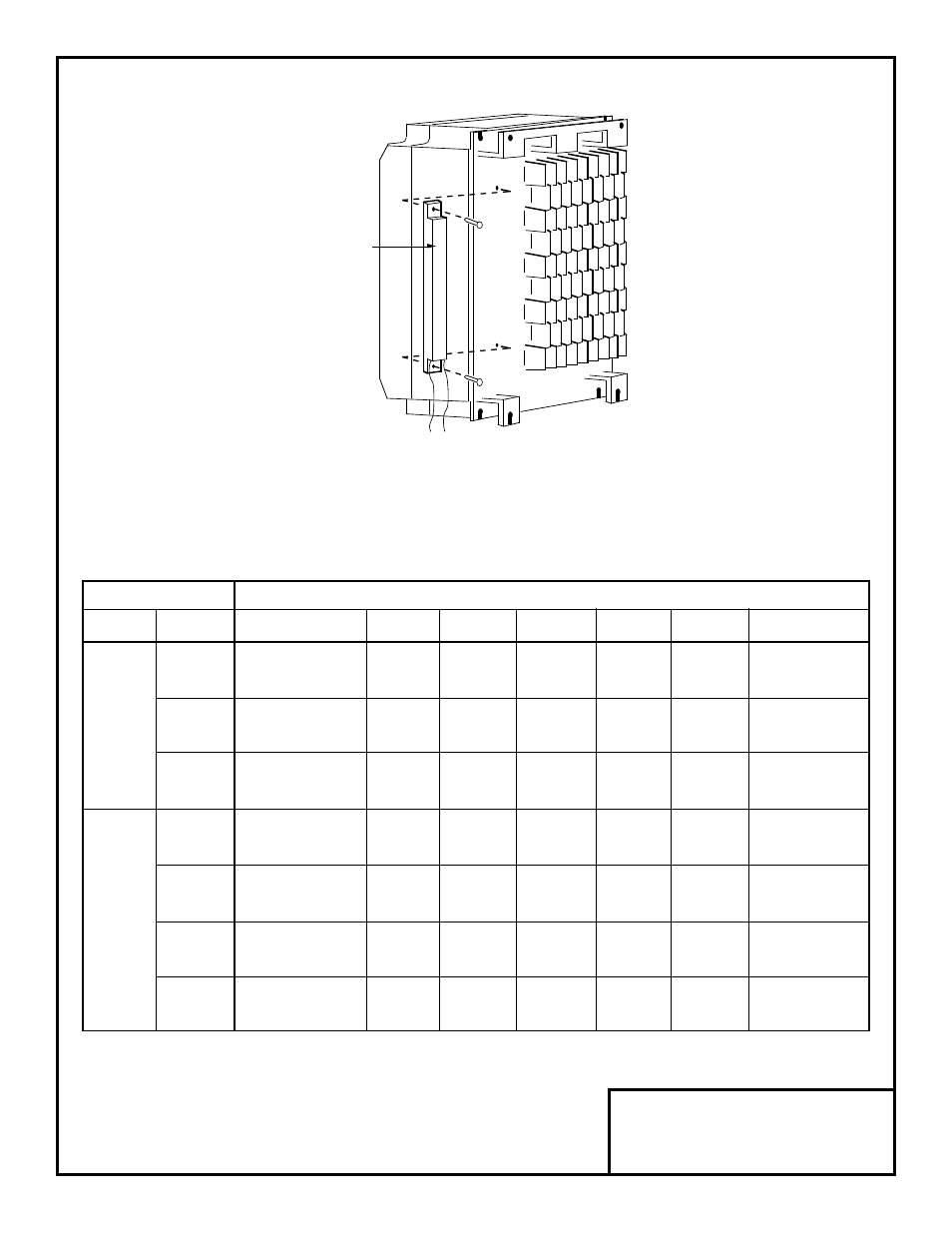
Figure 1. Mounting Braking Resistor on
Heat Sink of GPD 503 or VCD 703
* VCD 703, 460V 7.5HP drive does not use this part number Braking Resistor Unit,
but instead uses the part number listed for the 10HP drive.
BRAKING
RESISTOR