Yaskawa 303 Dynamic Braking User Manual
Page 5
DWG. NO. 02Y00025-0299
SHEET NO. 5 OF 6
EFF. 4/24/91
(m-df )
Refer to Sheet 1 for latest change.
9.
Open the braking resistor unit terminal box
for access to terminals. Connect the braking resistor
unit to the drive according to Table 2 and Figure 4.
ADJUSTMENTS
10.
The braking resistor (heat sink mounted) and
the remote-mount braking resistor unit require drive
re-programming.
a. For GPD 303: Program constant
no-20
to
1 X X X, which disables stall preven-
tion during decel.
b. For GPD 503:
(1). Program Sn-10 to
X X 1 X ,
which disables stall prevention during
decel.
(2). Braking resistor (heat sink
mount) only. Program Sn-11 to
X X X 1 ,
which enables overheat protection for the
braking resistor.
c. For VCD 703:
(1). Program On-03 to
X 0 X X ,
which disables overvoltage control
function. (This is the factory setting of
this digit.)
(2). Braking resistor (heat sink
mount) only. Program Sn-11 to
X X X 1 ,
which enables overheat protection for the
braking resistor.
11.
Reinstall and secure front cover on the drive
and close and secure the terminal box on the remote-
mount braking resistor unit.
12.
Place this instruction sheet with the drive
Technical Manual.
This completes the installation of this option.
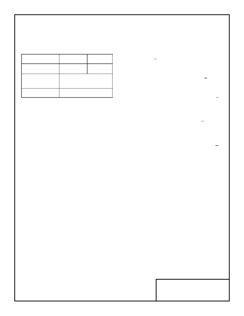
Table 2
Terminals
B, P
1, 2
✱
Lead Size (AWG)
12-10
18-14
✱
Lead Type
600V ethylene propylene
rubber insulated or equiv.
Terminal Screw
M4
✱
Power leads are for the braking resistor unit
generate high levels of electrical noise; these
signal leads must be grouped separately.
NOTE
External control components shown in Figure
4 are not supplied with the option. These
components are necessary for safe operation
of the Dynamic Braking option.