Warning – Yaskawa 303 Dynamic Braking User Manual
Page 4
DWG. NO. 02Y00025-0299
SHEET NO. 4 OF 6
EFF. 4/24/91
(m-df )
Refer to Sheet 1 for latest change.
RECEIVING
All equipment is tested against defect at the factory.
Report any damages or shortages evident when
equipment is received immediately to the commercial
carrier who transported the equipment. Assistance, if
required, is available from your MagneTek sales
representative.
STORAGE
If the option is not to be installed immediately, it must
be stored under the following conditions:
– Ambient temperature: -10 to +40° C.
– Protected from rain and moisture.
– Free from corrosive gases or liquids.
– Free from dust or metal particles.
– Clean and dry.
– Free from excessive vibration.
INSTALLATION
Preliminary Procedure
WARNING
HAZARDOUS VOLTAGE CAN CAUSE
SEVERE INJURY OR DEATH.
LOCK ALL POWER SOURCES
FEEDING DRIVE IN “OFF” POSITION.
1.
Disconnect all electrical power to drive.
2.
Remove drive front cover.
3.
Verify that voltage has been disconnected by
using a voltmeter to check for voltage at the incoming
power terminals.
NOTE
Since the drive has integral braking transis-
tors, the Dynamic Braking option only requires
addition of the braking resistor (heat sink
mount) OR the remote-mounting braking
resistor unit.
A. Braking Resistor (Heat Sink Mount) Installation
(not for GPD 303)
4.
Remove the drive from its mounting location,
for access to the rear of the heat sink.
5.
Mount the braking resistor on the back of the
drive’s heat sink, as shown in Figure 1.
6.
Reinstall the drive in its mounting position.
7.
Connect leads from the braking resistor to
drive terminals according to Figure 3.
B. Braking Resistor Unit Installation
8.
The braking resistor unit requires vertical
installation with ample clearance space (see Figure 2)
to achieve high cooling efficiency.
IMPORTANT
Since the braking resistor unit generates heat
during dynamic braking operation, install it in a
location away from other equipment which
emits heat.
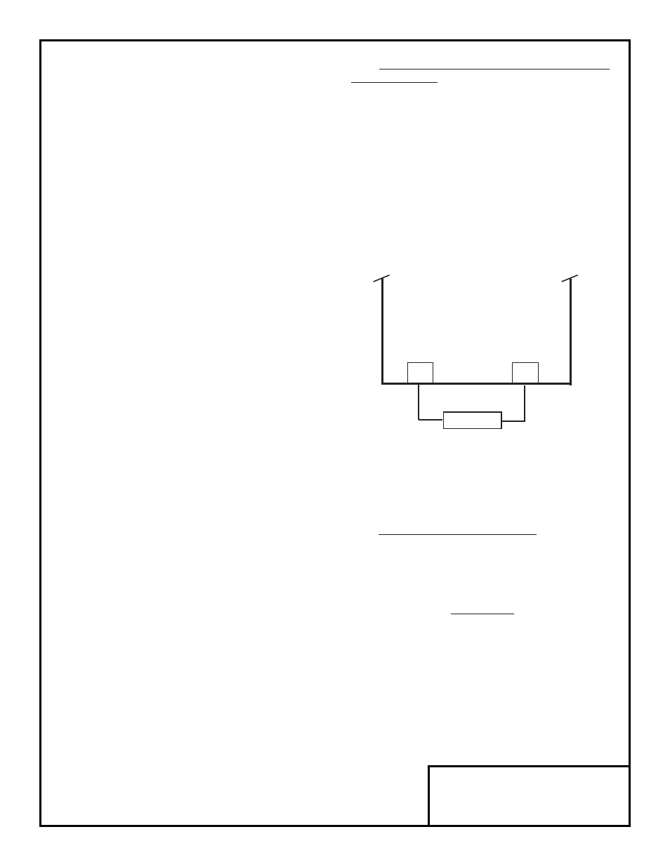
Figure 3. Lead Connections For Braking
Resistor (Heat Sink Mounted)
B1/+
B2
BRAKING
RESISTOR
P
B
GPD 503 or
VCD 703