Digital output option card do-08 – Yaskawa DO-08 User Manual
Page 2
Yaskawa Electric America, Inc. – www.drives.com
IG.AFD.56, Page 2 of 4
Date: 07/01/04, Rev: 04-07
Digital Output Option Card
DO-08
F7, G7,
GPD515/G5,
G5HHP
L1 (R)
L2 (S)
L3 (T)
T1 (U)
T2 (V)
T3 (W)
E
TD5
TD6
TD7
TD8
TD9
TD10
TD11
TD1
TD2
TD3
TD4
DO-08
Card
PHOTOCOUPLER
I M
MOTOR
MCCB
3CN
3CN
Attention must be paid to the diode polarity.
*
Be sure to install a surge absorbing circuit.
**
RELAYS
K2
K1
RC
RC
8RY
7RY
6RY
5RY
4RY
3RY
2RY
1RY
*
**
+24VDC
0V
200VAC
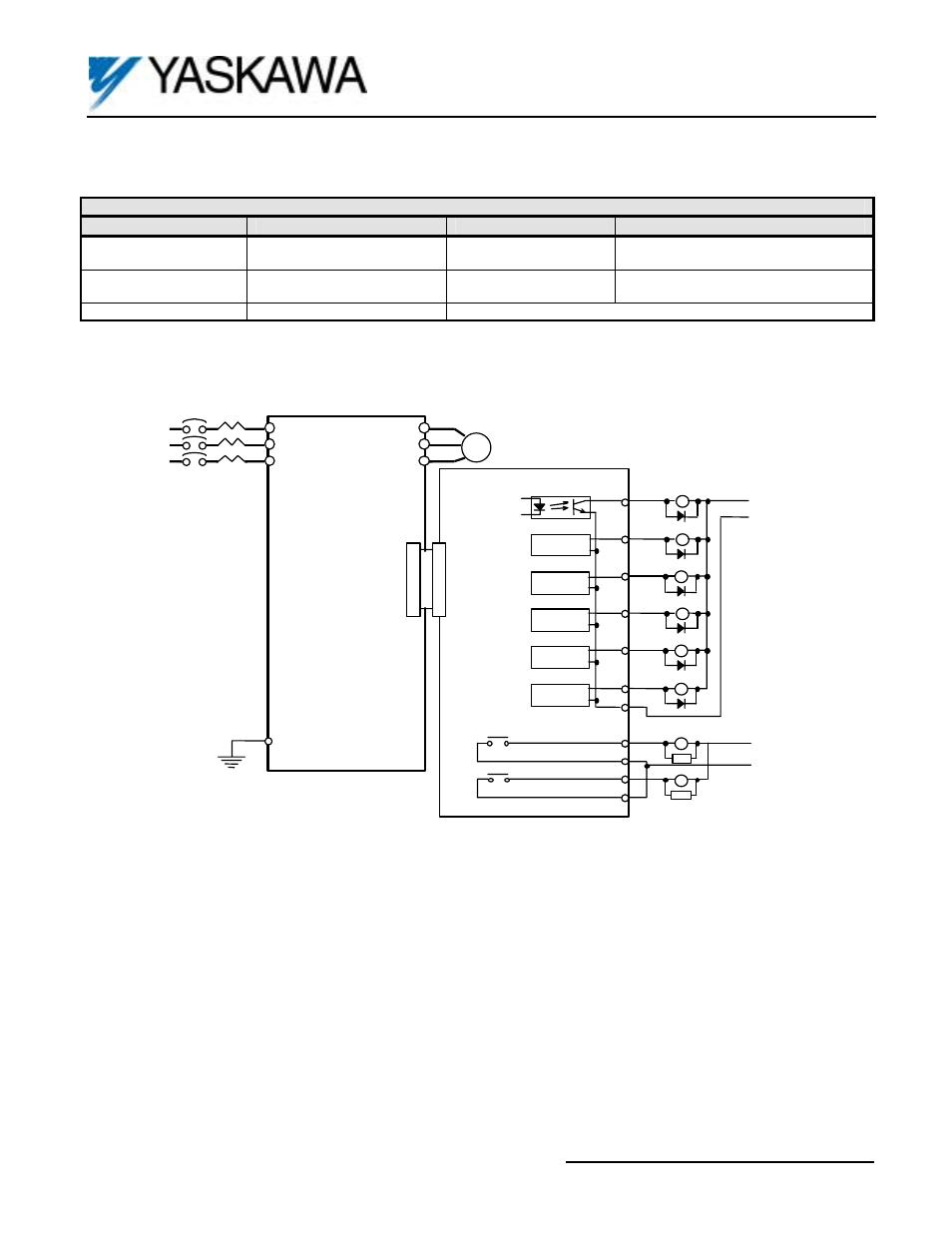
Figure 2. DO-08 Interconnection Diagram
Table 2. Terminal functions of Digital Output Card DO-08
Terminal
(1)
Type
Capacity
Output Signal
TD1 - TD4
Relay Contact:
2 outputs (independent)
250VAC, 1A or less
30VDC, 1A or less
See Table 4
TD5 - TD10
Photocoupler:
6 outputs (common emitter)
48VDC, 50mA or less
See Table 4
TD11
Output Common, 0V
(1) Terminal Screw Size = M3