Encoder feedback option card pg-x2 – Yaskawa PG-X2 User Manual
Page 3
Yaskawa Electric America, Inc. – www.drives.com
IG.AFD.60, Page 3 of 8
Date: 07/01/04, Rev:04-07
Encoder Feedback Option Card
PG-X2
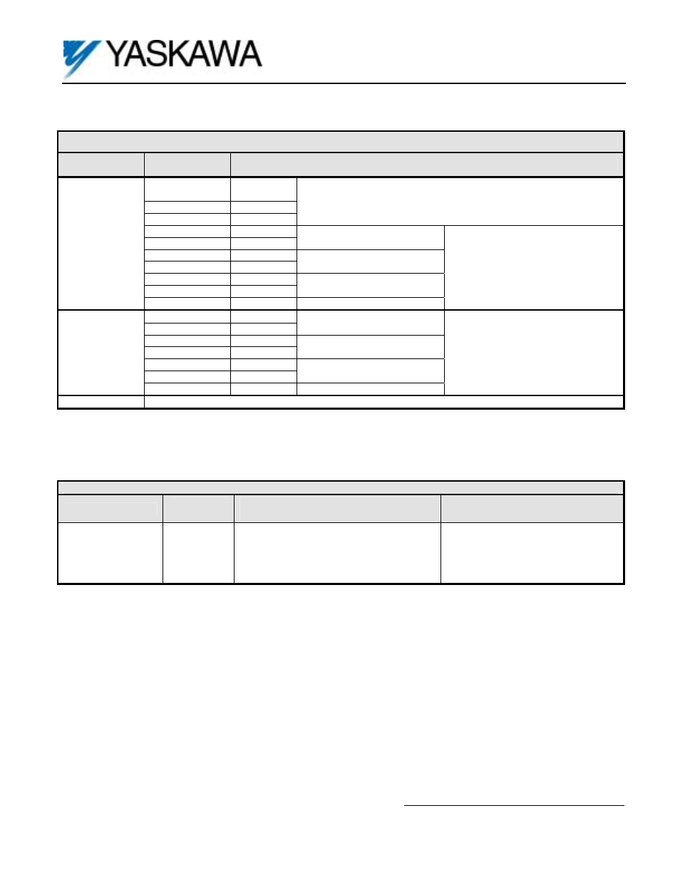
Table 1. Terminal Functions
Terminal
Block
Terminal
Number
Function
1 +12VDC
Power supply for Pulse Generator (PG).
Important: Use either +12V or +5V, but never both at the same time.
2
0V
+12VDC, 200mA max
3
+5VDC
+5VDC, 200mA max
4 +
5 -
A Pulse
6 +
7 -
B Pulse
8 +
9 -
Z Pulse*
TA1
10 0V
Common
Terminal
PG Signal Inputs
RS-422 Level Input
1 +
2 -
A Pulse
3 +
4 -
B Pulse
5 +
6 -
Z Pulse*
TA2
7
IG5
Isolated Common Terminal
Pulse Monitor Output
RS-422 Level Output
TA3
Shield Drain for Encoder Wiring
* Not required for standard software. May be required for custom software.
Table 2. Terminal and Wire Specifications
Terminal Symbol
Terminal
Screw
Clamping Torque
Lb-in (N-m)
Wire Range
AWG (mm
2
)
TA1, TA2
M2
1.8 to 2.2
(0.22 to 0.25)
26 to 16
(Stranded: 0.14 to 1)
(Solid: 0.14 to 1.5)