Installation diagrams, Hdr1 jumper positions, Front view – Yaskawa VS-616PC5/P5 Isolated 4-20mA Output Monitor Card CM-B2/P User Manual
Page 5: Side view, Cm-b2/p
Advertising
Page 5
VS-616PC5/P5 Option Instruction Manual: Isolated Monitor Card CM-B2/P
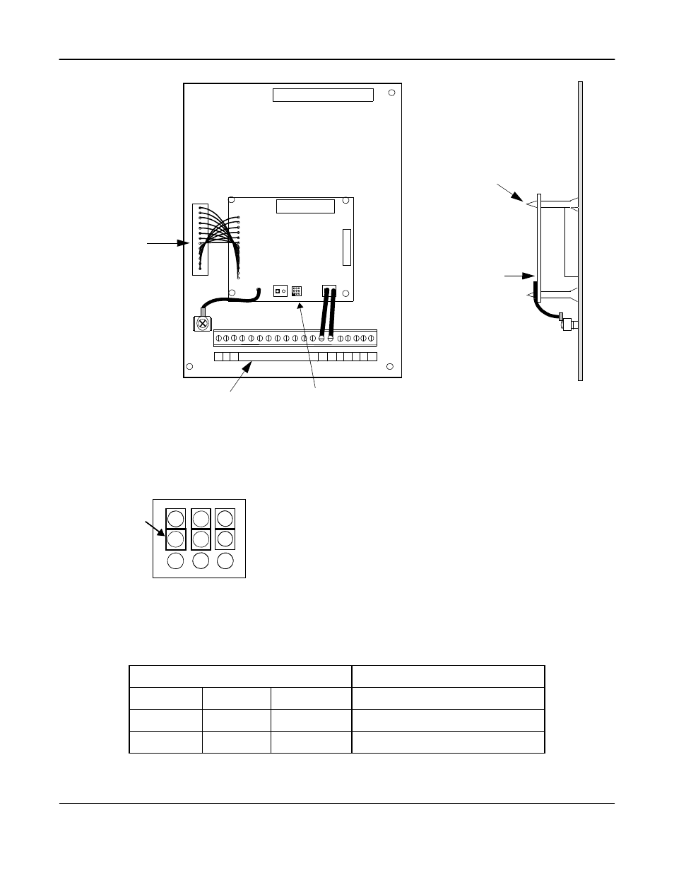
Note: Default 4 to 20mA
HDR1 Jumper Positions
HDR1 JUMPER POSITIONS
OUTPUT TB1
1-2
4-5
7-8
0 to 10 VDC
2-3
5-6
8-9
4 to 20 MA
1-2
4-5
8-9
0 to 20 MA
2
2CN option
connector
Fig. 2 Installation of Isolated Monitor Card CM-B2/P
Connector
terminal
FRONT VIEW
CM-B2/P
SIDE VIEW
Stand Off Posts (4)
CM-B2/P
TB1
TB2
1
HDR1
G
N
D
7
3
6
0
0
-D
0
1
2
0
C
O
D
E
N
O
.
TP1
Refer to Fig. 3
1
1
1
12
S1 S2
AM AC
S3
Fig. 3 Output Signal Configuration
3
6
9
2
5
8
1
4
7
JUMPER
for
HDR1
HDR1
3
6
9
2
5
8
1
4
7
HDR 1
Configures Output Signal at TB1
Note:
The three jumpers on the HRD1 are used to configure the
output signal at TB1. Refer to Table 2 for additional data.
Advertising