Wiring – Yaskawa VS-616PC5/P5 Isolated 4-20mA Output Monitor Card CM-B2/P User Manual
Page 7
Page 7
VS-616PC5/P5 Option Instruction Manual: Isolated Monitor Card CM-B2/P
WIRING
Refer to the following table for the external function terminals:
Wiring Connection Notes:
1. To prevent noise, use shielded wire as specified in Fig. 5. Separate the power circuits
(200VAC or greater) and the relay drive circuits from the control wires.
2. Wire lengths must be 164ft (50m) or less.
3. Connect the grounding lead wire (E) to the inverter control board grounding terminal E (G).
4. Applicable wire sizes for terminal block TBI and TB2 are as listed in the following table:
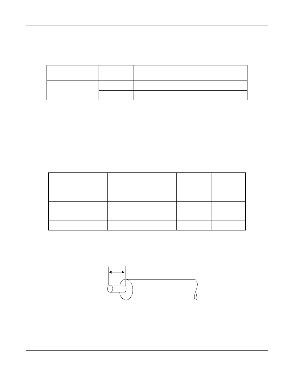
Stripping TB1 and TB2 Wires for Connection
The following figure shows the correct length of insulation to be stripped in order to connect the
wire to terminal blocks TB1 and TB2.
Cable Selection:
1. Cable that is too heavy exerts pressure on the option card and may cause failure.
2. Cable too thin may cause a poor connection or may prematurely break.
External Function Terminals
TERMINAL BLOCK
SYMBOL
PIN
NUMBER
FUNCTIONS
TB1
1
Isolated Monitor Output (+)
2
Isolated Monitor Output (-)
Wire Sizes
TYPE
[mm
2
]
AWG
I [A]
VAC [V]
Thin twisted wire
1
16
12
125
Solid Wire
1.5
16
12
125
UL
--
22-16
10
300
CSA
--
28-16
10
300
CSA
--
28-16
10
150
5.5mm
Fig. 6 Terminal Block TB1 and TB2 Side for Connecting Wire End