Interconnection diagram, Caution – Yaskawa VS-616PC5/P5 Isolated 4-20mA Output Monitor Card CM-B2/P User Manual
Page 6
Page 6
VS-616PC5/P5 Option Instruction Manual: Isolated Monitor Card CM-B2/P
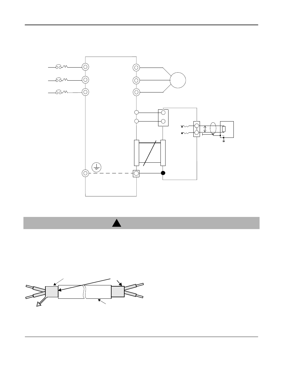
INTERCONNECTION DIAGRAM
Fig. 4 shows the mounting and interconnection between the inverter and the Isolated Monitor Card
CM-B2/P.
WIRING NOTES
1. Separate the wires for output signals (from the Isolated Monitor Card’s terminal block TB1) from
the main circuit wires and other power cables.
2. Use a shielded wire to connect output signals. Connect the wire as shown in Fig. 5 to prevent
noise interference.
Failure to observe these precautions may result in equipment malfunctions.
L1 (R)
L2 (S)
L3 (T)
IM
U (T1)
V (T2)
W (T3)
VS-616/PC5/P5
E (G)
AC
AM
2
1
2CN
2CN
E
Isolated Monitor Card
CM-B2/P
Fig. 4 Interconnection Diagram
250
?
P
Current
Output
TB1
TP1
TB2
12
!
CAUTION
Shielded Sheath
Armor
Fig.5 Shielded Wire
B
C
A
A. NEVER connect the wire’s shielded sheath when
connecting wires.
B. WRAP insulating tape around shielded areas and
wires where termination occurs.
C. CONNECT the shielded wire end to the Ground-
ing Terminal (E) on the inverter’s Terminal E (G).