Yaskawa EUS61501X User Manual
Page 10
3 Safety Procedure
10
YASKAWA TOEP YEAOPT 06 YASKAWA AC Drive - G5HHP Power Supply Unit with Charge LED Safety Precautions
Ensuring Safety Prior to Power Supply Unit Replacement
Refer to Recommended Safety Equipment in
to ensure safe handling of the Power Supply Unit prior to removal.
Summary of Safe Discharge Procedures
The Power Supply Unit may be discharged of hazardous voltages by use of three possible procedures. Under normal
conditions, assuming the drive is undamaged and fully operational, the Power Supply Unit may discharge to less than
50 Vdc within 10 minutes.
WARNING! Safe voltages must always be verified by use of a calibrated multimeter.
• DISCHARGE PROCEDURE 1: Wait 10 minutes after all power is turned off. Check for hazardous voltages with a
calibrated multimeter according to
. If voltage is less than 50 Vdc on bus capacitors and 0 Vac on 4PCB
TB1, the unit is safe from a shock hazard.
• DISCHARGE PROCEDURE 2: If hazardous voltages greater than 50 Vdc remain after 1 hour, then the Power
Supply Unit is defective and may take 8-12 hours or more to discharge. If waiting 8-12 hours is not possible then
perform Discharge Procedure 3.
• DISCHARGE PROCEDURE 3: Trained authorized personnel should use this procedure only after attempting
Discharge Procedure 1 and 2: Use a bleed resistor as shown in
to bleed off remaining hazardous voltage to less
than 50 Vdc.
PROCEDURE: Ensuring Safety Prior to Replacing the Power Supply Unit
DANGER! Electrical Shock Hazard
Disconnect and lock out all power to the drive, before servicing.
Voltage still remains in the drive capacitors even after the Power Supply Unit and drive are deenergized. The DC bus voltage and
Power Supply Unit voltage must be below 50 Vdc on bus capacitors and and 0 Vac on 4PCB TB1 before removal. To prevent
electric shock, wait at least the amount of time specified on the drive and measure the Power Supply Unit and drive DC bus to
determine safe voltages below 50 Vdc before touching any components.
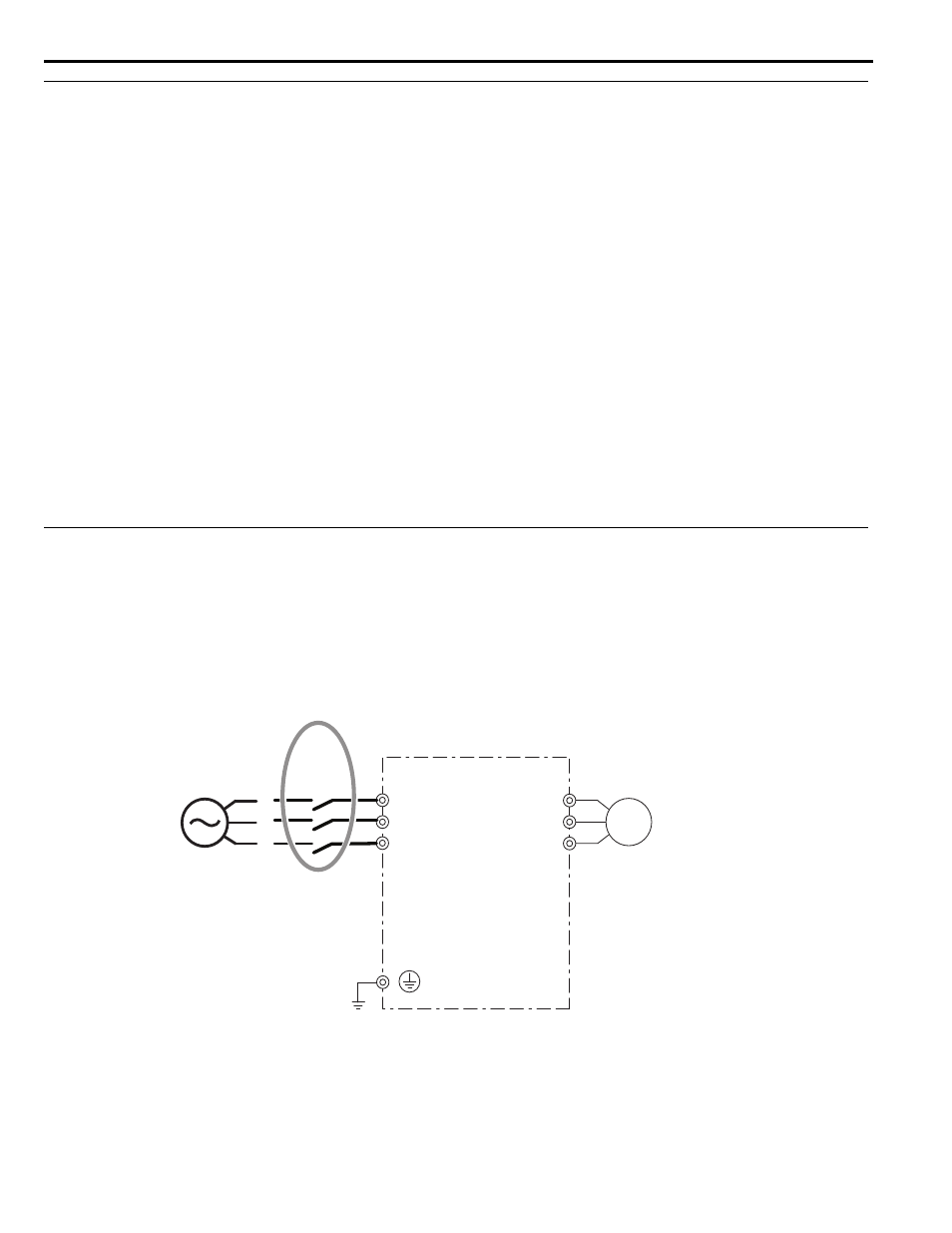
1.
Disconnect all power from the drive and lock out the main power source or switch. Also disconnect and lock out
all remaining external power sources to the drive including seperate control or I/O power supplies.
Figure 3
Figure 3 Deenergize All Power
R/L1
T/L3
S/L2
U/T1
V/T2
W/T3
Motor
AC input
Drive
Three-Phase
Power Supply
200 to 600 V
50/60 Hz
R
S
T
Main
Switch
(Depending on
model capacity)