Figure 4, Ab c, 3 safety procedure – Yaskawa EUS61501X User Manual
Page 11: Side view, Figure 4 verifying safe voltages
3 Safety Procedure
YASKAWA TOEP YEAOPT 06 YASKAWA AC Drive - G5HHP Power Supply Unit with Charge LED Safety Precautions
11
2.
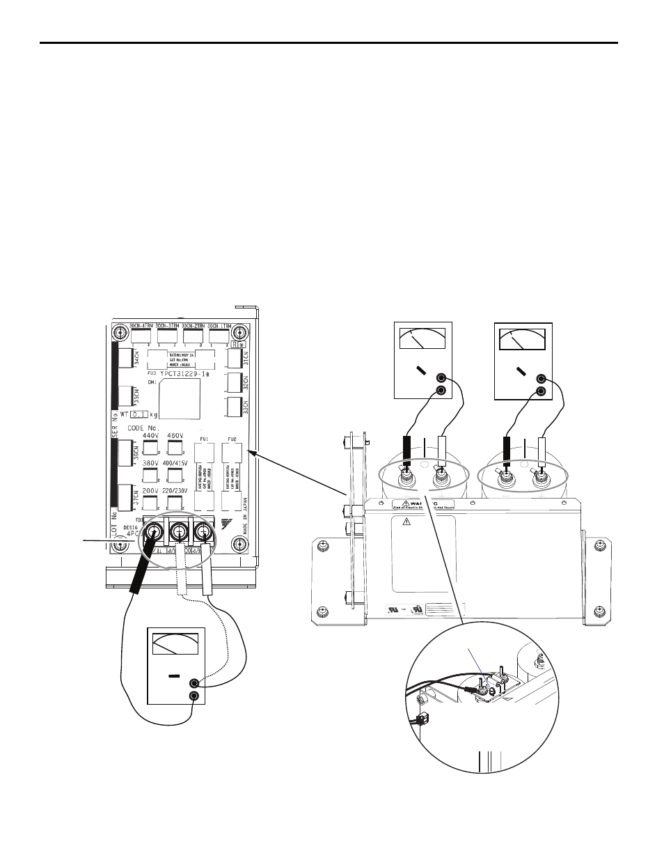
DISCHARGE PROCEDURE 1: Verify safe voltage levels: After waiting for at least 10 minutes, using protective
equipment recommended in
and a calibrated multimeter, check to ensure voltages are reduced to less
than 50 Vdc on bus capacitors and 0 Vac on 4PCB TB1. Refer to
for test points on the Power Supply
Unit.
2.a. Verify the drive’s main DC bus is below a safe voltage of 50 Vdc. The main DC bus voltages can be measured
across the (+1) and (-) terminals on the converter and inverter modules.
2.b. Check Test Point (A) on TB1 between r/l1 and s200 for 0 Vac, and between r/l1 and s400 for 0 Vac.
See
. Then proceed to Step 2.c.
If Test Point (A) is not at 0 Vac then recheck that all main power and external power sources are disconnected from
the drive.
2.c. Check Test Point (B) and then (C) on Power Supply Unit capacitors between (+) and (-) screw terminals
respectively for less than 50 Vdc. See
.
If Test Points (B) or (C) are not at a safe level of 50 Vdc or less then recheck again after waiting 10 minutes. If
voltage is still not less than 50 Vdc, proceed to Step 5.
Figure 4
Figure 4 Verifying Safe Voltages
WARNING
Risk of Electric Shock - Do Not Touch
The internal capacitor remains charged
after the power supply is turned off.
Disconnect all power to the drive before
servicing.
Wait until the status indicator LED is off,
and then measure DC bus voltage to
confirm a safe level below 50 Vdc before
servicing. The charge indicator LED will
extinguish when the DC bus voltage is
below 50 Vdc.
Failure to comply can result in serious
injury or death from electric shock.
MASS: 3.1 Kg
POWER SUPPLY UNIT
CODE NO.:
SER NO. : N4WXXXX-X-X
LOT NO.:
YASKAWA ELECTRIC CORPORATION
EUS6150XX
Side View
VDC
Verify less than 50 VDC
< 50 V
+
COM
VDC
Verify less than 50 VDC
< 50 V
+
COM
VAC
Verify 0 VAC
0 V
+
COM
A
B
C
W
ARNING
Risk of Electric Shock - Do Not T
ou
The internal capacitor remains charg
after the power supply is turned of
f.
Disconnect all power to the drive befo
servicing.
Wa
it until the status indicator LED is o
and then measure DC bus voltage to
irm
a safe level below 50 Vdc bef
The charge indicator LED w
the DC bus voltage i
lt in serious
k
W
ARNING
Risk of Electric Shock - Do Not
Touch
Charge LED
The Charge LED PCB
is present on power
supply models:
EUS61501 and EUS61502