Yaskawa iQpump1000 AC Drive User Manual
Page 1 of 5
Step
1
Wiring and setting up an iQpump1000 Duplex System
Page 1 of 5
The following
procedure is a
supplement to
documentation
supplied with this
equipment and
will guide the user
in wiring multiple
iQpump1000
drives for a
multiplex pump
application.
DANGER!
Improper wiring
can and will cause
bodily harm as
well as damage to
the equipment.
Follow good
wiring practices
and applicable
codes when
installing the
system. Ensure
that the mounting
of the various
components are
secure and that
the environment,
such as extreme
dampness, poor
ventilation etc. will
not cause system
degradation.
Read this Quick
Start Procedure
and other
documentation
provided with the
iQpump1000
thoroughly before
attempting
installation.
Yaskawa America, Inc., 2121 Norman Drive South, Waukegan, IL 60085, (800) YASKAWA (927-5292) Fax (847) 887-7310, [email protected], www.yaskawa.com, Document Number: TM.iQp1000.03 05/29/2014 © Yaskawa America, Inc.
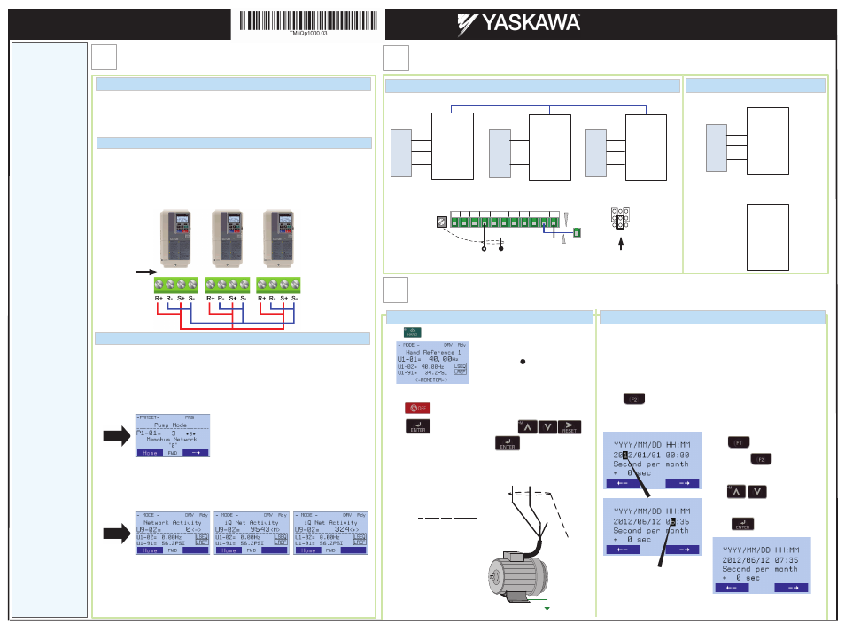
Transducer Wiring
This step shows how to connect and wire an iQpump1000 Duplex or Triplex System using a
transducer for each iQpump1000 drive.
Before making any connections M
MAKE SURE POWER TO THE iQpump1000 IS TURNED
OFF! Next remove the terminal cover to gain access to the control terminals. (Step 1.)
APPLICATION DESCRIPTION
1. Jumper terminals (R+ to S+) and jumper terminals (R- to S-) terminals on each individual
iQpump1000 drive according to Fig. 1.
2. Use shielded communication cable to connect the iQpump1000 drives in a daisy chain the
(R+ to S+, R- to S-) terminals between each iQpump1000 drive.
3. Power-up the iQpump1000 Drives.
4. Set drive node address parameter H5-01 (see figure 1.) for each iQpump1000 drive.
5. Program each iQpump1000 parameter P9-25 (Highest Node Address) to 2 for a duplex
system and 3 for a triplex system.
6. Program each iQpump1000 parameter P1-01 set to 3 (Pump Mode) to:
7.
Cycle power to ALL iQpump1000 drives on the network.
8. Check U9-02 and verify that :
- No iQpump1000 drives have a value of "0" <->.
- All iQpump1000 drives receive valid data and U9-02 changes regularly.
- At least one iQpump1000 drive has the unit <M>, while the rest have the unit <+>.
9. If there is an iQpump1000 drive with "U9-02 = 0 <->" as shown above:
- Check communication wiring as shown on first page of this report
- Verify the serial communication address (H5-01) as shown on first page of this report
- Confirm P9-25 and P9-27 settings on all drives. P9-25 should be set to the highest
H5-01 address and at least one iQpump1000 drive should have P9-27 = 0.
- Cycle power to all iQpump1000 drives.
MULTIPLEX NETWORK PROGRAMMING
NETWORK WIRING
Fig. 1.
Install drive P3 for
triplex system.
P1
P2
P3
H5-01=1
H5-01=2
H5-01=3
Drive Node
Address
!
H5-01 is the drive
node address
parameter, see
test below.
After the power has been turned
OFF, wait at least five minutes
until the charge indicator
extinguishes completely before
touching any wiring, circuit
boards or components.
Next swap any two of the three
motor leads.
DANGER !
Push
and the HAND
LED should be
ON
.
Push
on the Digital Operator; the display should read
on the Digital Operator;
If the direction is not correct, then power down the iQpump1000
and follow instructions below.
Press to access Hand Speed. Use
to change hand Speed value. Press to save value.
CHECK PUMP ROTATION
REAL-TIME CLOCK SETUP
To change direction
of motor rotation
swap any
two
of the
three
motor leads.
3Ø Induction
motor
Connect
frame to
ground
(U/T1)
(V/T2)
(W/T3)
This step shows how to setup the iQpump1000 real-time clock for first use.
Note: If clock is not set the drive can still be programmed and operated, but
ALM light will flash every 30s and showing C
Clock Not Set message.
Power up the drive and set the real-time Clock. The real-time Clock setup
screen will appear at first power up.
Press to set the clock.
Note: After the real-time clock is set the real-time clock setup screen will
not show again unless parameter o4-17 is set to “Set”.
Use to move cursor to
The left and to move
cursor to the right
use to adjust.
When date and time are set
press to save.
·
Clock is set in 24hr mode.
·
Do N
NOT adjust sec per month.
Example: Jun 12
th
2012, 7:35am
Notes:
The motor should now be operating in the correct direction of pump.
Step
2
Pump Rotation Check / Change Motor Direction / Real Time Clock Setup
Step
3
Brown or Red: +Power (1)
Black: Output
4 – 20mA (2)
Cable
Shield
+V AC A1 A2 A3 FM AM AC RP AC 24V
2-Wire, 4-20mA Transducer
E(G)
Install link (AC-SN) when
using transducer.
SN
Factory
Installed
(Factory
Default)
Jumper located
inside the drive on
the terminal board
2
nd
row of user
terminal shown here.
A1 A3
A2
V
I
iQpump1000 Network
iQpump1000
P2
iQpump1000
P3
iQpump1000
P1
System
Pressure
Feedback
+24V
A2
AC
T
ra
n
sd
u
ce
r
*
+24V
A2
AC
+24V
A2
AC
P9-02 = 2
P9-02 = 2
P9-02 = 2
T
ra
n
sd
u
ce
r
*
T
ra
n
sd
u
ce
r
*
Connect the transducer to iQpump1000 P1.
USE SINGLE NETWORK TRANSDUCER
ONE TRANSDUCER PER iQPump1000 DRIVE
iQpump1000
P2, P3, ...
+24V
A2
AC
P9-02 = 3
iQpump1000
P1
+24V
A2
AC
T
ra
n
sd
u
ce
r
*
P9-02 = 2
For all other iQpump1000 drives set parameter
P9-02 to 3 for Network Transducer.
Install drive P3 for
triplex system
Install drive 3 for
Triplex System
* 3-Wire, 4-20mA Transducer
iQpump1000 AC Drive
Multiplex Quick Start Procedure