Page 3 of 5, Low city pressure, Low and high psi levels – Yaskawa iQpump1000 AC Drive User Manual
Page 3
Step
5
Low City Pressure
Page 3 of 5
Yaskawa America, Inc., 2121 Norman Drive South, Waukegan, IL 60085, (800) YASKAWA (927-5292) Fax (847) 887-7310, [email protected], www.yaskawa.com, Document Number: TM.iQp1000.03 05/29/2014 © Yaskawa America, Inc.
This function is used with low suction inlet pressure switches on
pressure booster systems for buildings that get their main water
supply from a municipality.
This pressure switch enables and disables the pump system
when the inlet supply is at a low suction pressure and when
running the pump system in this condition will cause damage.
An inlet pressure switch is wired directly into the drive using one
of the digital input terminals. If the pressure switch is active and
sufficient pressure is available, the drive system will operate
normally.
If the pressure switch indicates that incoming pressure is too
low, the drive will take the following actions:
• The drive will be forced into a sleep-like state (coast to stop).
• Any drives staged in multiplex mode will immediately coast to
stop.
• The selected alarm “Low City Pressure”, “Low Suction
Pressure”, or “Low Water In Tank” will be displayed
(determined by P4-24).
Setup Procedure
1. Set all other parameters required for the application such as
PI control loop, sleep, motor, and I/O parameters.
2. Set one digital input for the low suction inlet pressure switch
(H1-xx = 73). Wire the switch to this terminal.
3. Configure the terminal for a normally open / closed switch
type using parameter P4-21.
4. Configure the delay times for activating and removing the
alarm in parameters P4-23 and P4-24. This can be used to stop
the drive from cycling too frequently if the pressure varies a lot.
5. Select the alarm message that will be displayed when a Low
City condition is detected using parameter P4-24. Options
include “Low Cty Pressure”, “Low Suction Pres”, and “Low Watr
In Tank”.
Low City
Pressure
User Terminals
Link
S1 S2
S3 S4 S5 S6 S7 S8
SN SC SP
Wiring Diagram: Low City Pressure
Example: Terminal S7: H1-07 = 73
Parameter
Value Description
Reference
P4-21
0
Low City Input
Select
Selects the type of pressure
switch connected to the “Low City
Press” digital input S7
(H1-07 = 73).
0: Normally
Open
1: Normally
Closed
P4-22
5 sec.
Low City
On-Delay
Time
Sets the amount of time a “Low
City Pressure” condition needs to
be present before the drives will
stop.
P4-23
15 sec.
Low City
Off-Delay
Time
Sets the amount of time a “Low
City Pressure” condition needs to
be absent before the drives will
restart.
P4-24
0
Low City
Alarm Text
Selects the alarm message that
will be displayed when a LowCity
condition is detected.
0: Low City Pressure
1: Low Suction Pres
2: Low Water In Tank
This function allows the user to set low and high system
pressure levels measured off the feedback transducer.
The low (P1-08) and high (P1-11) feedback levels are set as
an absolute value in the system units selected by P1-02.
Low Feedback Detection, enabled when:
- Parameter P1-08 is set greater than zero
When the low feedback detection is enabled and the feedback
signal falls below the low feedback detection level (P1-08) the
iQpump1000 will annunciate the low feedback condition based
on the Low Feedback Selection (P1-10).
High Feedback Detection, enabled when:
High feedback detection is enabled when:
- Parameter P1-11 is set greater than zero
When the high feedback detection is enabled and the feedback
signal rises above the high feedback detection level (P1-11) the
iQpump1000 will annunciate the high feedback condition based
on the High Feedback Selection (P1-13).
Step
6
Low and High PSI Levels
Parameter Value Description
Reference
L5-40
0
Low Feedback
Fault Retry
Selection
Determines whether the LFB-
Low Feedback fault can be
auto- restarted.
0: No retry
1: Retry
P1-08
0.0
PSI
Low Feedback
Level
Sets the lower detection level
for the PID feedback.
Range: 0 ~ 6000.0
(system units P1-02)
P1-09 10
sec
Low Feedback
Level Fault
Delay Time
Sets the amount of delay time
from when the low feedback is
detected until the drive faults
out on a “LFB-Low Feedback”
fault. (effective only when P1-
10 = 0) Range 0 ~ 3600 sec
P1-10
0
Low Feedback
Selection
Selects how the drive will re-
spond during the “Low Feed-
back” condition.
0: Fault (and Digital Out)
1: Alarm (and Digital Out)
2: Digital Out Only (
H2-0x = 97)
Parameter Value Description
Reference
L5-41
0
High Feedback
Fault Retry
Selection
Determines whether the HFB-
Low Feedback fault can be
auto- restarted.
0: No retry
1: Retry
P1-11
155.0
PSI
High Feedback
Level
Sets the upper detection level
for the PID feedback.
Range: 0 ~ 6000.0
(system units P1-02)
P1-12 10
sec
High Feedback
Level Fault
Delay Time
Sets the amount of delay time
from when the high feedback is
detected until the drive faults
out on a “HFB-High Feedback”
fault. (effective only when P1-
13 = 0) Range 0 ~ 3600 sec
P1-13
0
High Feedback
Selection
Selects how the drive will re-
spond during the “High Feed-
back” condition.
0: Fault (and Digital Out)
1: Alarm (and Digital Out)
2: Digital Out Only
(H2-0x = 96 )
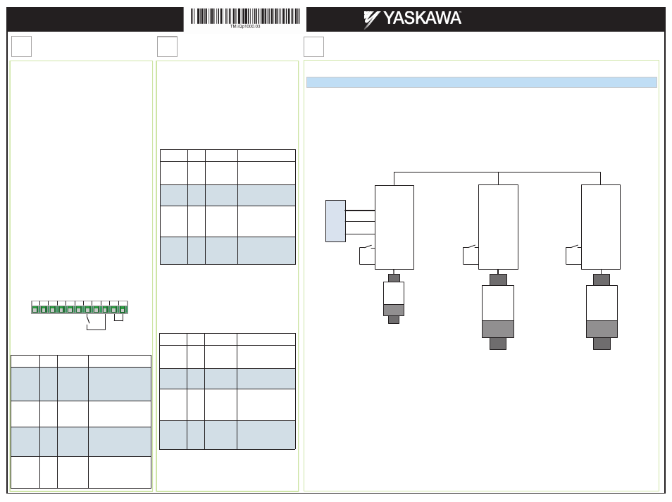
This step shows examples of how to setup an iQpump1000 Multiplex Systems using a jockey pump.
Duplex System with Jockey Pump Example – Single Transducer
Example shows pump system with the following requirements:
- One small pump (the Jockey pump) 7.5 HP will run the system during off-peak times.
- Two larger pumps (15 HP) will run the system when the demand is higher.
- The Jockey pump should not run when the two larger pumps are running.
- Larger pumps lead-lag will alternate every run cycle
- The feedback scale is 200 PSI.
- System setpoint is 120 PSI.
- Low city pressure switch installed on input S7.
- There is only one feedback transducer in the system.
Pump B
Pump C
iQpump1000 Network
Jockey
Pump
iQpump1000
P2
iQpump1000
P3
iQpump1000
P1
System Pressure
Feedback
+24V
A2
AC
T
ra
n
sd
u
ce
r
*
7.5 HP
15 HP
15 HP
+24V
A2
AC
+24V
A2
AC
S7
SN
S7
SN
S7
SN
Low City
Pressure
Switch
Low City
Pressure
Switch
Low City
Pressure
Switch
Transducer shown is a three wire, 4-20mA output.
For a two wire transducer only connect 24V and A2. (see step 9.)
*
Step
7
Adding a Jockey Pump to an iQpump1000 Duplex System
iQpump1000 AC Drive
Multiplex Quick Start Procedure