Initial switches and potentiometers settings – Yaskawa Drive Simulator User Manual
Page 5
TM.AFD.Simulator Page 5
4. Initial Switches and Potentiometers Settings:
• Default positions for switches and pots to minimize the faults on the connected control cards:
SWITCH TOP MIDDLE
BOTTOM
S1-S12
X
S21 X
S22-S24
X
S19 & S20
X
S14 & S16
Set Toward Internal Sources only.
S13 X
S15 X
S17 X
S18 X
S38 X
S35 X
S32
Set to Low Inductance position for most cases.
S28 X
S26 & S30
X
S25 & S29
X
S27 & S31
First position only ON for 32PPR.
S36
Set as to control card’s Power ratings in O2-04*
Potentiometer Leftmost Middle Rightmost
VR1-VR3
X
VR10 X
VR12
X
VR11
X**
VR6 X
VR7 X
VR8 and VR9
X
VR4 X
VR5 X
X
* Please note that when mounting a control card to the unit, in order to keep all the settings inside control card
unchanged, you might need to try every single setting of S36 and recycle the power each time by S37 push button, to
check which code matches with the control card’s. This will take about 1 minute at the worst case.
** VR11 will cause OV or UV faults, when rotated toward left or right ends. Please adjust it around the middle until
the faults go away automatically.
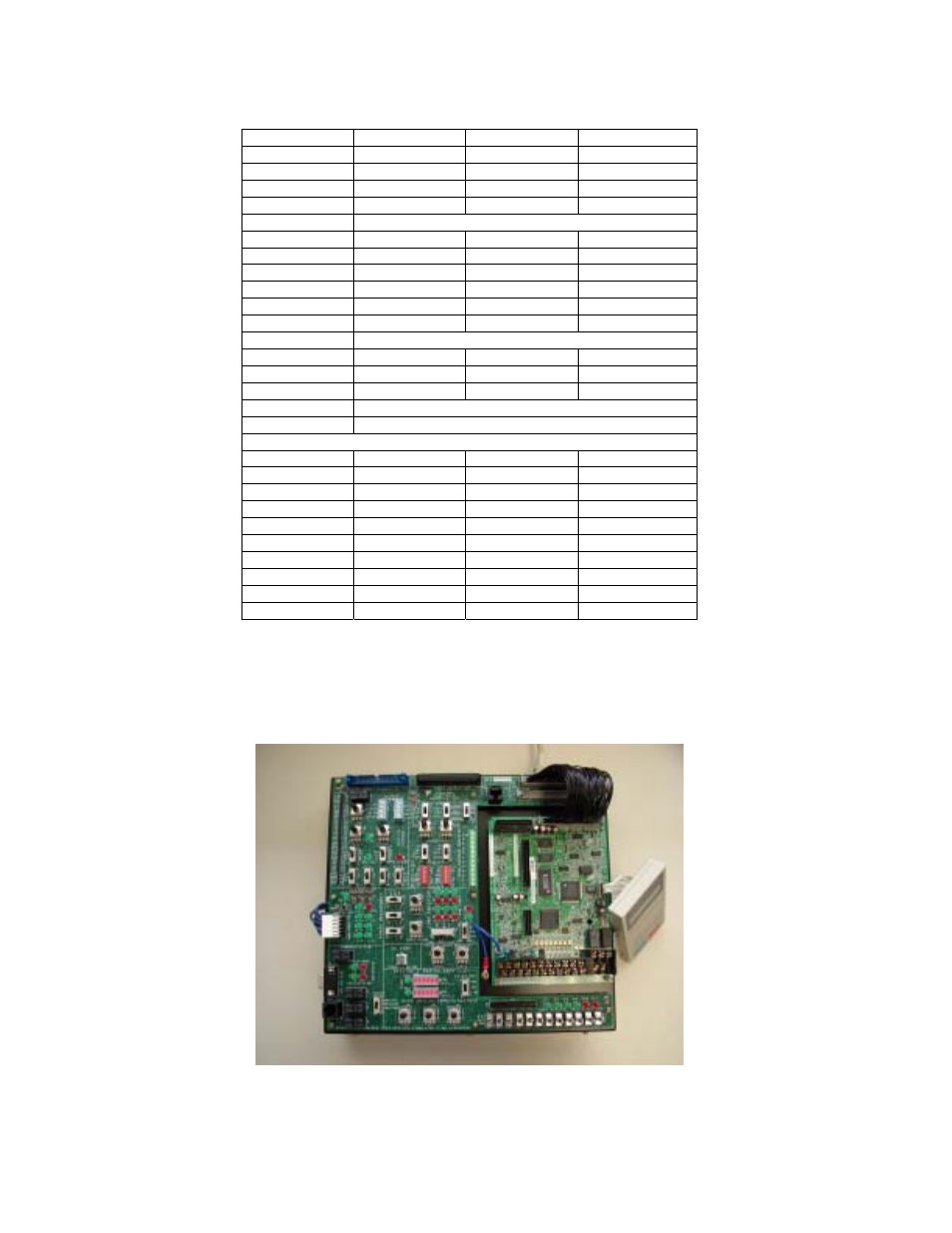
Figure 4: Simulator with G5/P5/PS5 control card installed