Yaskawa Drive Simulator User Manual
Page 8
TM.AFD.Simulator Page 8
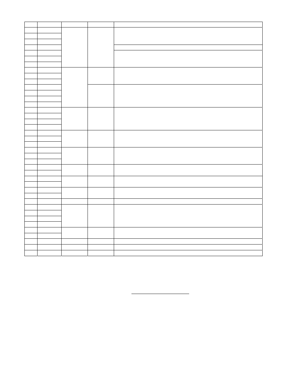
Pin Label
Type
Level
Description
1 IU_OUT
2 IV_OUT
3 IW_OUT
Emulated motor current signals from the three phases individually,
amplitude-controlled and phase-controlled (power factor or inductive load)
through VR6 and VR7.
4
IUVW
Emulated sum of the three phase currents inside the drive.
5 PF_U
6 PF_V
7 PF_W
Analog ±15VDC
Emulated motor current signals from the three phases individually, only
phase-controlled (load power factor or the level of inductance) through
VR6, without amplitude control.
8 UPWM
9 VPWM
10 WPWM
±15VDC
Emulated IGBT outputs from the drive to run a motor. Later these power
signals will be fed to the power-factor and level control circuits for
emulating the actual motor itself.
11 NUL
12 NU2L
13 PUL
14 PU2L
Digital
5V-TTL
Sine-weighted, multi-level PWM signals, generated by the control card-
under-test. All four signals from one phase leg (U) are brought here. NU2L
and PU2L are only available from two-level drives though, such as G7-
400V class and will be off for regular one-level drives. See note 2 below.
15 US1
16 US2
17 US3
18 US4
Digital 5V-TTL
The power rating of the drive or US-CODE, provided to the, will be
actually present at these pins. These signals are high-active or positive
logic. These four signals constitute a half-byte or nibble code with US4
being the MSB and US1 the LSB. This code is a drive parameter content .
19 THM
20 VDET
21 CUV
Analog ±10VDC
Analog control signals from drive’s power section to the control card.
THM reports the heat sink temperature, VDET reports the DC Bus voltage
and CUV monitors the power supply voltage to control card.
22 AIN2
23 MONT1
24 MONT2
Analog ±10VDC
Analog signals from the user I/O terminal, AIN2 is reference input 2 (4-
20mADC, when disconnected from the drive, 1-5VDC, when connected).
MONT1 and MONT2 are the two user analog outputs from the drive.
25 PLS_IN
26 PLSOUT
Digital 24VDC
PLS_IN is the pulse reference input of the drive, fed by the unit pulse
generator (0-24VDC/15Hz-25kHz). PLSOUT is drive’s pulse output.
27 BTRA
28 BTRON
Digital 5V-TTL
BTRA is the drive’s command to turn on the Braking transistor, in case of
rising DC Bus voltage and BTRON is the drive’s response feedback for it.
29 MCOPL
30 MCON
Digital 24VDC
MCON is the drive’s command to close the soft-start relay, when its
capacitors are charged up and MCOPL is the drive’s response feedback.
31
FAN
Digital
5V-TTL
Drive’s command to control the heat sink blowers during motor is running.
32 VCLL
33 VCHL
34 VCFL
35 FUL
Digital 5V-TTL
Low Active or negative logic signals to report drive’s power section status.
VCLL and VCHL report the power supply safe voltage levels in specific
drives, VCFL (SCL in G5) reports power supply or braking transistor
failure and FUL reports the main DC Bus fuse failure to the drive.
36 PG1CKO
37 PG2CKO
Digital 5V-TTL
TTL-Resolved independent sweep clocks to feed the PG1 and PG2
encoders from any selected source at double the encoder frequencies.
38
PGCKIN
Digital
5V-24V
External Clock source input to both encoder emulators, routed by S26/S30.
39
REC5V
Supply
5V-TTL
Main 5V supply to control card under test, recycled by S37 push button.
40
IP24VDC
Supply
24VDC
Unregulated 25VDC supply for external use, 50mA maximum load.
Table 1: The simulator signal descriptions available at the Test Points connector, J1
Note 1: Although all the test point signals are protected against shorts or overloads but can still distort the normal
logical operations of the unit circuitries or even cause damage to them by improper connections or shorting.
Note 2: These 4 PWM signals from the control card, NUL, NU2L, PUL and PU2L should be probed very carefully
otherwise they can cause damage to the control card and/or unit motor emulator circuitry, in case of interference.
• External Access Port - EAP:
1. Connector: Standard dual-row header, .100” pitch, 40-pins, shrouded/protected
2. Loading: All short-circuit protected, measurement impedance 10kOhm-min. See Note 3.
3. Application: Automatic hardware/software test setups, PLC-driven controls, Load Emulation
4. Available Signals: Both inputs and outputs, digital and analog signals are provided at this
connector. Most outputs are open-collector/24V and most inputs are 5V-TTL compatible.