Irritrol RainSensor User Manual
Page 5
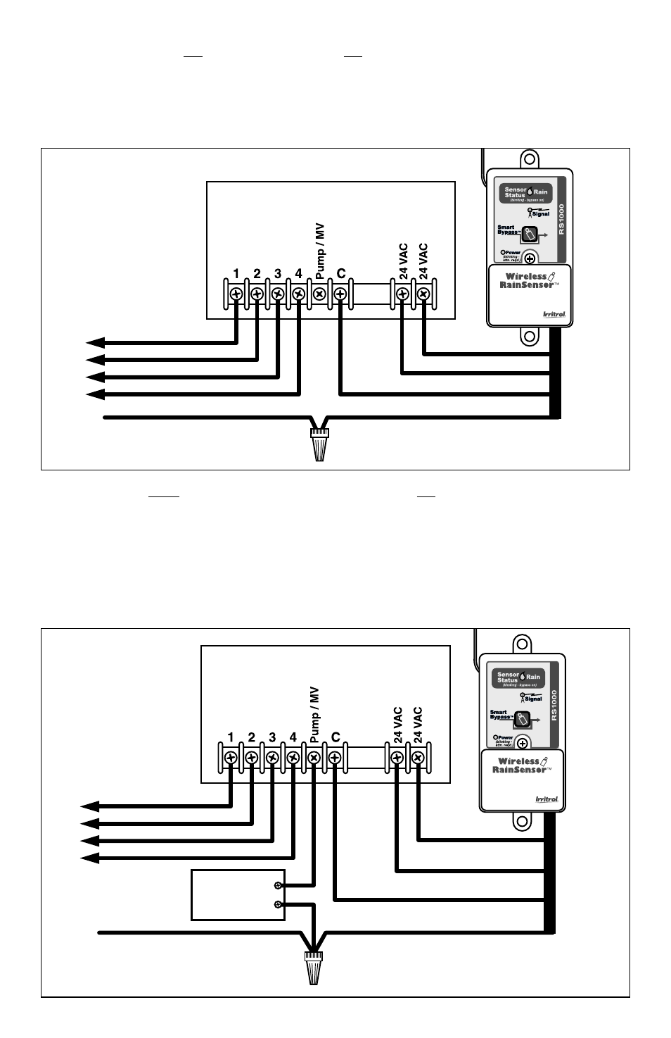
B. Controllers with no sensor inputs and no pump start or master valve:
Refer to Figure 7. Disconnect the valve common wire from the controller’s common
terminal (generally marked “C”, “Com”, or “VC”). Join this wire to the White wire
using a wire connector. Attach the Brown wire to the valve common terminal.
Note: The yellow wire is not used in this application.
C. Controllers with pump start or master valve and no sensor inputs:
Refer to Figure 8. Disconnect all common control wires from the common
terminal(s) of the controller (generally marked “C”, “Com”, or “VC”). Join these wires
to the White wire using a wire connector. (Be sure to include the common wire from
the Pump Start Relay in this connection). Attach the Brown wire to the common
terminal.
Note: The yellow wire is not used in this application.
5
Figure 7
Red
Common From Valves
To Valves
White
Wire Connector
Irrigation System Controller
Brown
Red
Figure 8
Red
Common From Valves
To Valves
White
Wire Connector
Pump Start
Relay
Irrigation System Controller
Brown
Red