Rainfall adjustment, Vent ring adjustment, Installing the sensor/transmitter – Irritrol RainSensor User Manual
Page 7
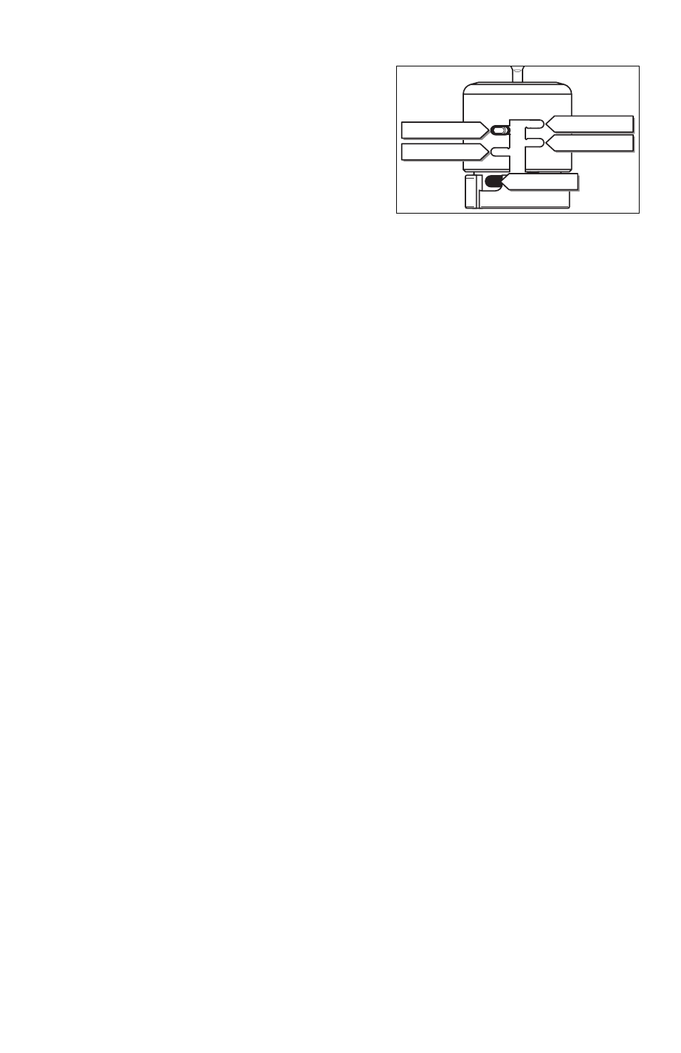
Rainfall Adjustment
The Sensor/Transmitter can be adjusted to
respond when it has detected nominal rainfall in
the following amounts: 1/8" (3mm), 1/4" (6mm),
1/2" (12mm) or 3/4" (19mm). Carefully rotate the
Rainfall Adjustment Cap so the pins are positioned
in the desired slots. Be sure to align the slots and
pins properly, as this adjustment does not require
excessive force. See Figure 10.
Note: Avoid using the 1/8" (3mm) setting in high humidity conditions.
Vent Ring Adjustment
Closing the vent holes will slow the sensor dry-out rate, uncovering the holes will
accelerate the dry-out rate. For most installations, a fully closed vent is appropriate.
Installing the Sensor/Transmitter
Note: If installing Wireless RainSensor model RFS1000 for freeze detection, please
refer to additional instructions provided on page 8.
Testing Signal Strength at the Installation Site
The Receiver’s Signal Indicator provides an indication of the strength of the last valid
received signal. Prior to testing the Sensor/Transmitter in its final location, clear the
Signal Indicator first so the test will represent the signal as received during the final
check. To clear the Signal Indicator from previous tests, simply press the Smart
Bypass button once, then once again to exit the bypass mode.
Prior to final placement, test the Sensor/Transmitter signal by lightly pressing and
holding the spindle as described in “Initial Receiver Testing” on page 6.
Note: If the location of the Sensor/Transmitter is not providing a valid signal to the
Receiver, verify Sensor/Transmitter operation at close range and choose another
mounting location. For additional information, refer to “Improving Reception”
on page 10.
Tip! If the Receiver is not visible to the installer, turn on a watering zone which is
visible from the installation location and the activation of the Sensor/Transmitter will
shut off the “test” zone. Please note that the manual activation cycle of some
controllers bypasses the sensor inputs. You will need to run an automatic/timed
watering program for these types of controllers.
7
Figure 10
1/4" (6mm)
1/2" (12mm)
Vent Hole
3/4" (19mm)
1/8" (3mm)