Pe n – KACO Powador-gridsave User Manual
Page 21
Advertising
Installing the device
Operating instructions Powador-gridsave_EN
Page 21
Authorised electrician
X2
X1
F1 F2 X7
X4
St
1
St
2
St
3
2
3
5
4
1
6
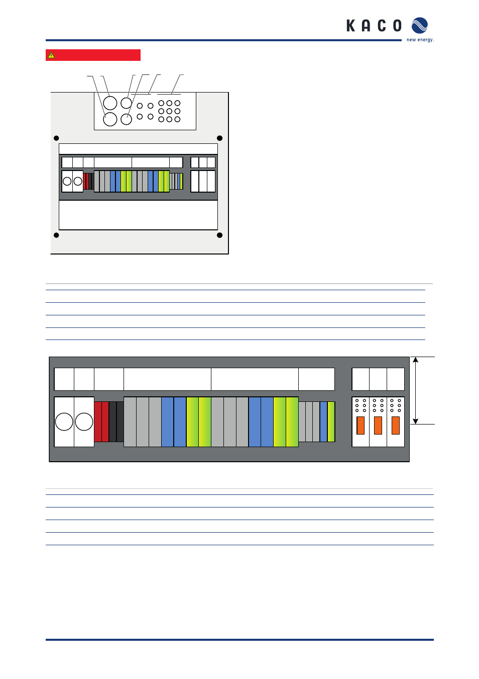
Figure 12: View from above of the connection area
Key
1
AC grid input (M40 cable fitting)
4
Network interface (M32 cable fitting)
2
AC grid output (M40 cable fitting)
5
Inverter input (M16 cable fitting)
3
Inverter output (M32 cable fitting)
6
Other connections (M16 cable fitting)
F1 F2
X7
X4
St
1
St
2
St
3
L1 L2 L3
N
PE L1 L2 L3 N N PE PE
X1
X2
PV
+
PV
-
L1 L2 L3 N PE
32A 32A
PE
N
Cust
omer
connec
tion
Figure 13: View from above of the connection area
Key
X1
AC grid input (main junction box / meter)
X7
PV generator input
X2
AC grid output (building electrical system)
F1, F2
Phase bridging fuse
X4
Inverter output
St 1-3
Potential-free contacts control outputs
Advertising