Chapter 3, Board layout, Jumper settings – Lanner LEC-7106 User Manual
Page 13
Advertising
13
Board Layout
Chapter 3
Embedded and Industrial Computing
Jumper Settings
Microphone-in Audio Jack (MIC1)
Line-out Audio Port (LIN1)
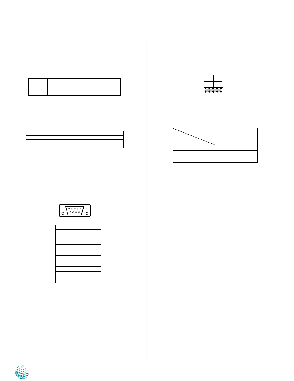
RS-232 Serial Port (COM1~COM4): It is an RS-232 port
through the D-SUB9 connector.
SC1T1/SC2T1/SC3T1/SC4T1: Select COM1/COM2/
COM3/COM4 Pin 9 (ring indicator) signal
Switch Combination
Protocol
SW1/SW4
+5V
1-2
+12V
3-4
RI (default)
5-6
6 7 8 9
1 2 3 4 5
Pin No.
signal
Pin No.
signal
1
GNd_AUd
2
MIC_OUT_L
3
GNd_AUd
4
GNd_AUd
5
MIC_OUT_R
Pin No.
signal
Pin No.
signal
1
GNd_AUd
2
FRONT_OUT_L
3
GNd_AUd
4
GNd_AUd
5
FRONT_OUT_R
Pin No.
signal
Rs-232
1
dCd
2
Rxd
3
Txd
4
dTR
5
GNd
6
dsR
7
RTs
8
CTs
9
RI (ring indicator)
The Main Board
1
3
5
2
4
6
Advertising