Chapter 2, System components, Block diagram – Lanner LEC-7106 User Manual
Page 7: Processor, Embedded and industrial computing
Advertising
7
System Components
Chapter 2
Embedded and Industrial Computing
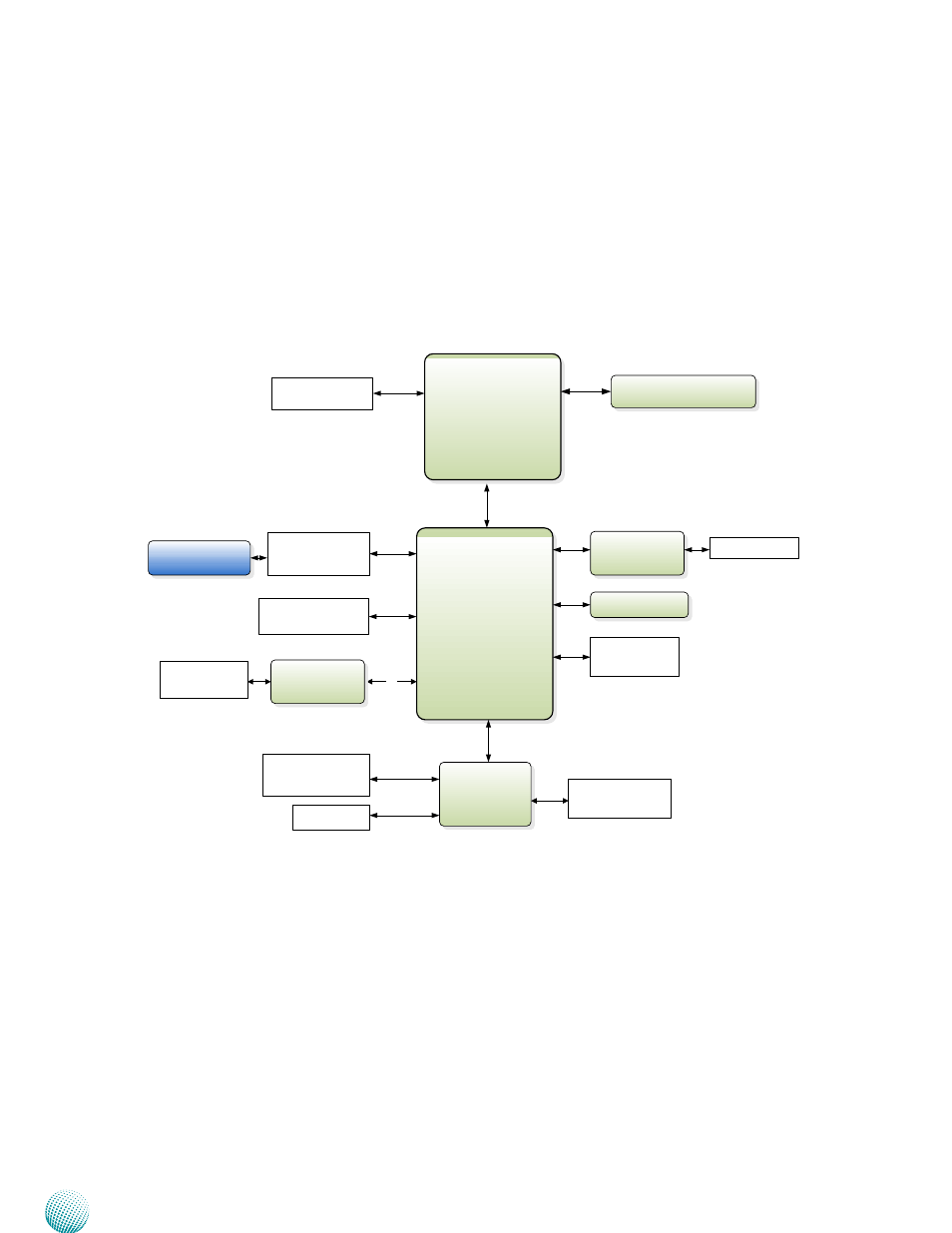
Block Diagram
The block diagram depicts the relationships among the
interfaces and modules on the motherboard..
Processor
Intel
D525
(BGA)
PCH
ICH8-M
D
M
I2
x4
DDR3 800/1066
1x SO-DIMM
Winbond
W83627UHG
H/W Monitor
WDT
SATA II
USB
Flash BIOS
SPI
Mini-PCIe Socket with
SIM card Reader
GbE Controller
Intel i210AT
1x PCIe
LAN1
RJ-45
USB 2.0
Type A x 4
Pin header x 2
SATA Connector
2x SATA connectors
PCIe
USB 2.0
VGA
LP
C
1x 2.5" HDD/SSD
Serial Port
4x DB-9 for RS-232
MIC/Line-in
Jack
HD
HD Audio
VIA VT1718S
PS/2 Connector
Keyboard/Mouse
Advertising