Chapter 2, System components, Front components – Lanner LEC-7106 User Manual
Page 8
8
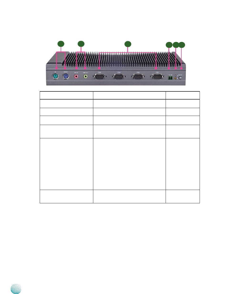
System Components
Chapter 2
Embedded and Industrial Computing
Component
Description
Pin Definition
Reference
F1 Keyboard and Mouse
Connector
PS/2 keyboard and mouse connector
KB1, MS1 on page 14
F2 MIC IN/LINE OUT
An USB type A connector.
MIC1, LIN1 on page
13
F3 Serial Ports COM1~ COM4
Serial ports through the DB-9 connector.
These ports support RS-232 communication.
COM1~COM4 on
page 13
F4 Power-on Switch
A power-on switch through the Phoenix
contact for distant power-on/off control
J12 on page 15
F5 Power LED (Green) and HDD
(Yellow)
HDD
Blinking: data access activities
•
Off: no data access activities
•
Status
A programmable dual green/orange LED
which can be used for indicating system
status.
Power
On: The computer is on.
•
Off: The computer is off .
•
F6 Power Button with dual LED
ATX Power-on button with LEDs: Standby
mode in Red; Power-on mode in Green
Front Components
F3
F1
F4
F5 F6
F2