Common antenna styles – Linx Technologies TRM-915-DTS User Manual
Page 23
– –
– –
40
41
Common Antenna Styles
There are hundreds of antenna styles and variations that can be employed
with Linx RF modules. Following is a brief discussion of the styles most
commonly utilized. Additional antenna information can be found in Linx
Application Notes AN-00100, AN-00140, AN-00500 and AN-00501. Linx
antennas and connectors offer outstanding performance at a low price.
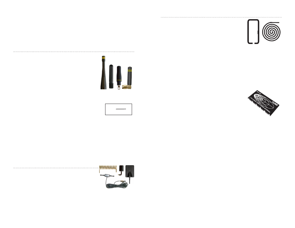
Whip Style
A whip style antenna (Figure 53) provides
outstanding overall performance and stability.
A low-cost whip can be easily fabricated from
a wire or rod, but most designers opt for the
consistent performance and cosmetic appeal of
a professionally-made model. To meet this need,
Linx offers a wide variety of straight and reduced
height whip style antennas in permanent and
connectorized mounting styles.
The wavelength of the operational frequency determines
an antenna’s overall length. Since a full wavelength
is often quite long, a partial ½- or ¼-wave antenna
is normally employed. Its size and natural radiation
resistance make it well matched to Linx modules.
The proper length for a straight ¼-wave can be easily
determined using the formula in Figure 54. It is also
possible to reduce the overall height of the antenna by
using a helical winding. This reduces the antenna’s bandwidth but is a great
way to minimize the antenna’s physical size for compact applications. This
also means that the physical appearance is not always an indicator of the
antenna’s frequency.
Specialty Styles
Linx offers a wide variety of specialized antenna
styles (Figure 55). Many of these styles utilize helical
elements to reduce the overall antenna size while
maintaining reasonable performance. A helical
antenna’s bandwidth is often quite narrow and the
antenna can detune in proximity to other objects, so
care must be exercised in layout and placement.
L =
234
F
MHz
Figure 53: Whip Style Antennas
Figure 54:
L = length in feet of
quarter-wave length
F = operating frequency
in megahertz
Figure 55: Specialty Style
Antennas
Loop Style
A loop or trace style antenna is normally printed
directly on a product’s PCB (Figure 56). This
makes it the most cost-effective of antenna
styles. The element can be made self-resonant or
externally resonated with discrete components,
but its actual layout is usually product specific.
Despite the cost advantages, loop style antennas
are generally inefficient and useful only for short
range applications. They are also very sensitive to changes in layout and
PCB dielectric, which can cause consistency issues during production.
In addition, printed styles are difficult to engineer, requiring the use of
expensive equipment including a network analyzer. An improperly designed
loop will have a high VSWR at the desired frequency which can cause
instability in the RF stage.
Linx offers low-cost planar (Figure 57) and chip
antennas that mount directly to a product’s PCB.
These tiny antennas do not require testing and
provide excellent performance despite their small
size. They offer a preferable alternative to the often
problematic “printed” antenna.
Figure 56: Loop or Trace Antenna
Figure 57: SP Series
“Splatch” Antenna