Reset to factory default, Hardware reset, Voltage supply rise time – Linx Technologies TRM-915-DTS User Manual
Page 8: The cmd line
– –
– –
10
11
Reset to Factory Default
It may be necessary to reset the non-volatile registers to their factory
defaults. To reset the module, hold the CMD line low and cycle power to
hardware-reset the module. The CMD line must remain low for a minimum
of 450ms after resetting the module. Once the CMD line is released, the
module’s non-volatile registers are reset to factory defaults.
Hardware Reset
Pulling the RESET line low places the module’s protocol controller in
hardware reset. In this state, the module is in a safe, stalled state. If the
voltage supply rise time is greater than 1ms, the module should be held in
reset until Vcc reaches 2.7V. There are many reset supervisor ICs that can
accomplish this task.
The RESET line must be held low for at least 20µs to cause the module to
enter reset. Normal operation is restored when this pin is returned high.
Voltage Supply Rise Time
The power supply rise time is extremely important. It must rise from ground
to 2.7V in less than 1ms. If this specification cannot be met, an external
reset supervisor circuit must be used to hold the module in reset until the
power supply stabilizes. Failure to ensure adequate power supply rise time
can result in loss of important module configuration information.
The CMD Line
The CMD line is used to inform the module where incoming UART data
should be routed. When the line is high or left floating, all incoming UART
data is treated as payload data and is routed to the transmitter to be sent
over the air. If the CMD line is low, the incoming UART data is routed to the
command parser for processing. Since the module’s processor looks at
UART data one byte at a time, the CMD line must be held low for the entire
duration of the command plus a 20µs margin for processing. Leaving the
line low for additional time (for example, until the ACK byte is received by
your application) does not adversely affect the module. If RF packets are
received while the CMD line is active, they are still processed and output on
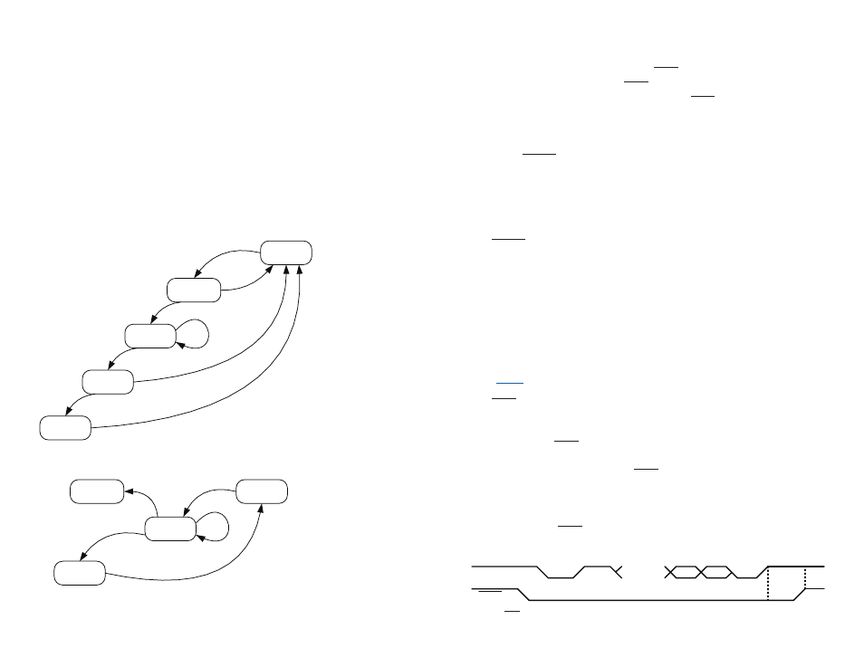
the module’s UART. Figure 10 shows this timing.
RXD
CMD
0xFF
...
B1
B0
≥20µs
Figure 10: CMD Line Timing
When a module transmits a packet, all other modules on the same channel
receive the packet, check the packet for errors, determine whether the
received group ID matches the local group ID, and compare the sender’s
master/slave flag to its internal setting. If the packet is error free, the group
IDs match, and the master/slave rules are satisfied (if peer to peer is
selected in the receiving module, this test passes regardless), the module
decodes the data and outputs it on the RXD line.
The primary state when the module is not actively transmitting or receiving
data is the IDLE state. While in this state, the receiver is enabled and the
module is continuously listening for incoming data. If the module detects
a pre-amble and valid start-code, it enters the RX HEADER state. Figure 8
shows the receiver state diagram and Figure 9 shows the transmitter state
diagram.
IDLE MODE
RX HEADER
RX DATA
CRC
UART TX
RF ISR
RX TIMEOUT
HEADER OK
RX DONE
RF ISR
DATA LENGTH < MTU
CRC FAILED
PACKET
QUEUED
IDLE MODE
TX WAIT
CSMA
DATA LENGTH
≥ MTU
OR TX TIMEOUT
RX HEADER
RF ISR
UART RX
DATA LENGTH < MTU
TX COMPLETE
Figure 8: DTS Series Transceiver Receiver State Diagram
Figure 9: DTS Series Transceiver Receiver State Diagram